English
Unbox
LicheeRV Nano Package Introduction
The LicheeRV Nano is available in four versions based on networking capabilities:
- Standard Version (B): Comes without any networking accessories.
- Ethernet Version (E): Features an onboard 100M Ethernet port for wired network connections.
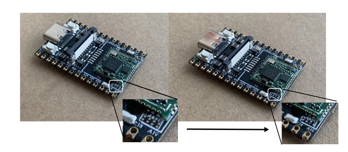
- WiFi Version (W): Equipped with an onboard WiFi6/BT5.2 module. By default, the BT5.2 functionality is not enabled. To activate Bluetooth capabilities, it's necessary to solder four 0201 resistors in the specified location or use a 2B pencil to create a short circuit in the designated area.
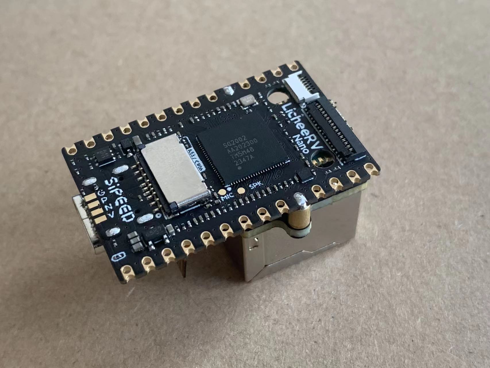
The WiFi Ethernet (WE) version features an onboard WiFi 6/BT 5.2 module and comes with an Ethernet module that connects to the development board via standoffs and ribbon cables.
We also offer the following accessory:
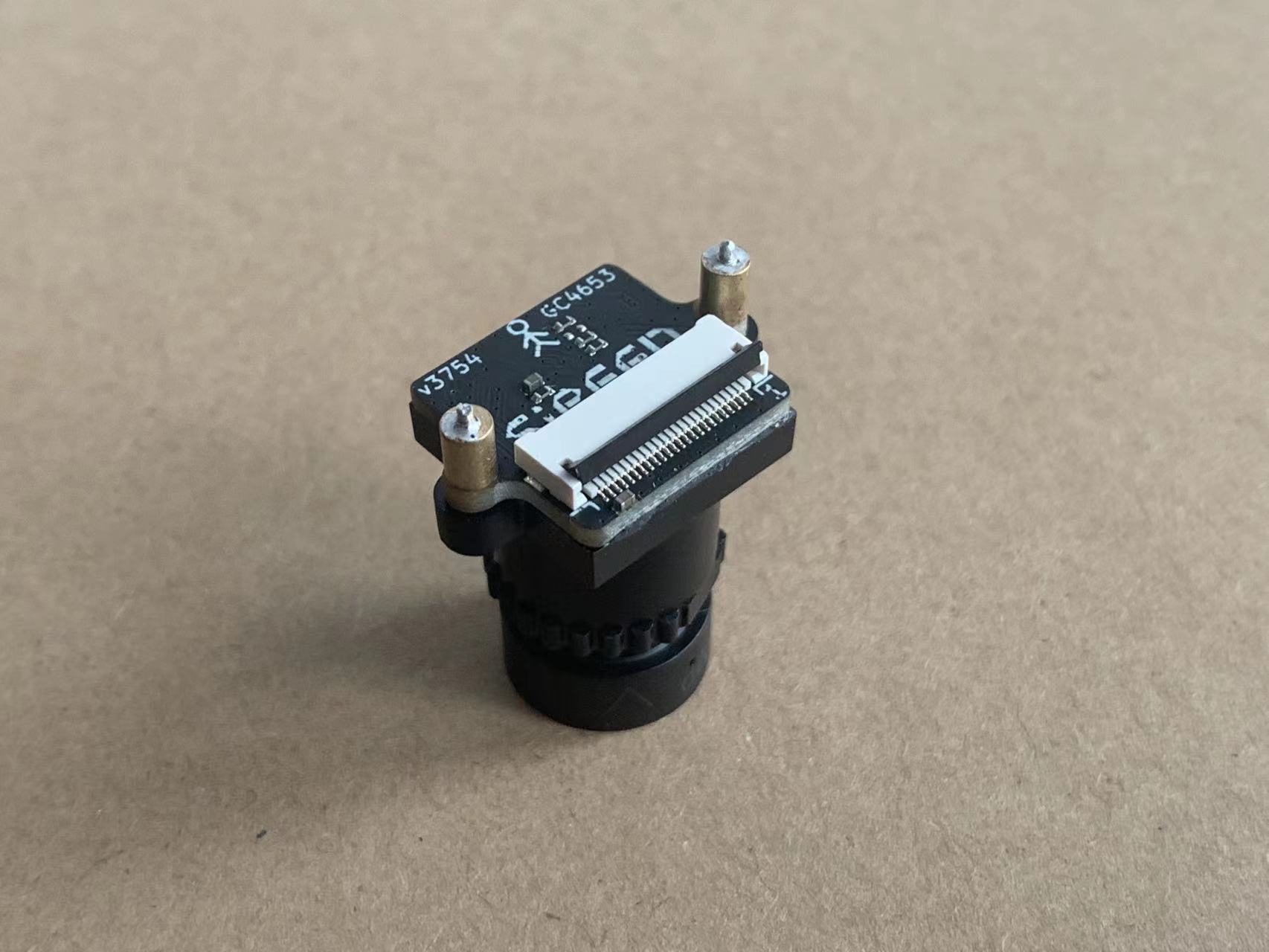
- Camera
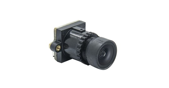
- Camera
The camera (model 3754) features non-short-circuiting screw holes on both sides for secure mounting. It is recommended to fix the standoffs to the fifth pad for optimal stability.
3-inch Display Screen

- The display features a resolution of 480*845 and supports touch functionality. The package includes a touch screen adapter board and a ribbon cable for easy integration.
- 5-inch Display Screen

- This display boasts a resolution of 480*845 and does not support touch functionality. The ribbon cable can be directly connected to the LicheeRV Nano 31Pin screen interface for seamless integration.
- 7-inch Display Screen

- The display features a resolution of 800*1280 and supports touch functionality. The ribbon cable can be directly connected to both the LicheeRV Nano 31Pin screen interface and the 6Pin touch interface, ensuring easy setup and integration.
- 10-inch Display Screen
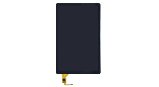
- The display features a resolution of 800*1280 and supports touch functionality. The package includes a touch adapter board and a ribbon cable for easy setup. The screen ribbon cable can be directly connected to the LicheeRV Nano 31Pin screen interface, ensuring seamless integration.
- Raspberry Pi Camera Adapter Ribbon Cable (Coming Soon)

- Raspberry Pi Standard 15Pin Camera to LicheeRV 22Pin CSI Camera Interface Adapter
Installation Guide
Installing the WE Module
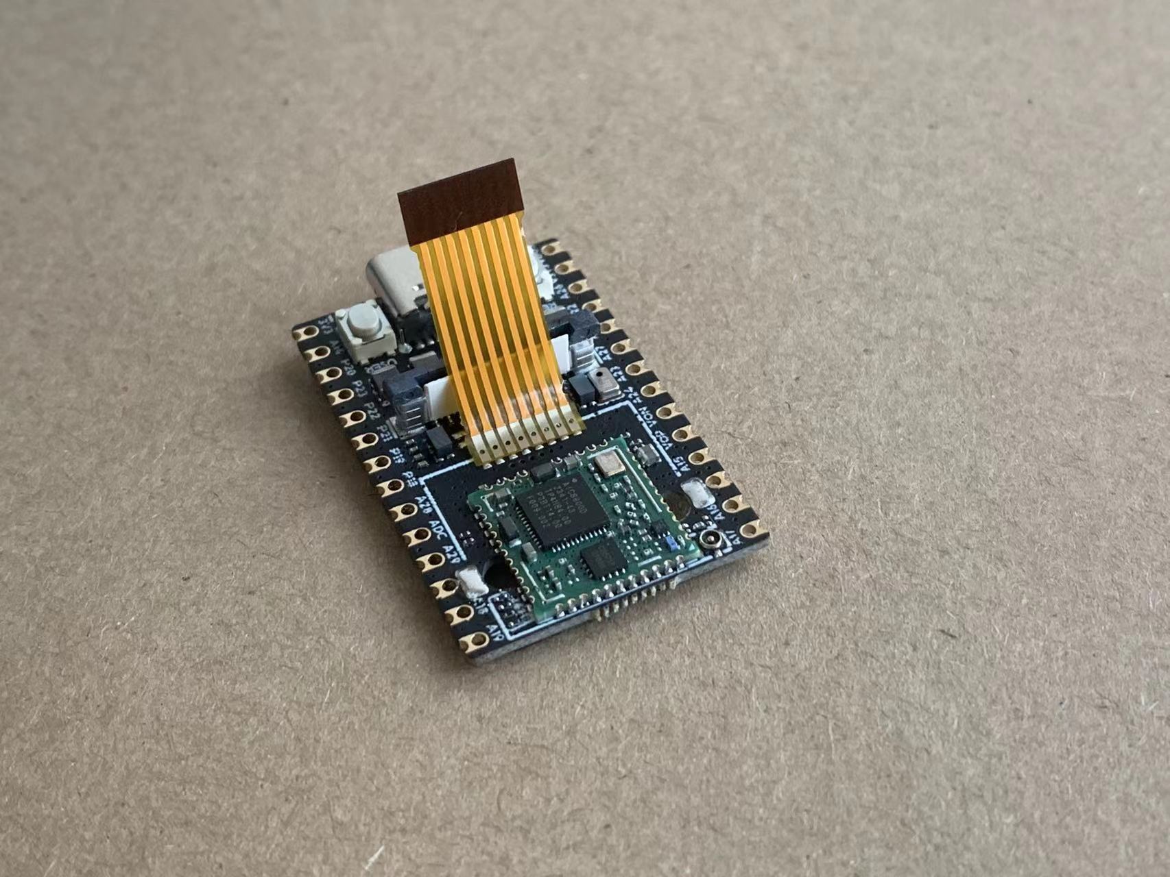
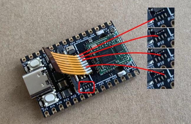
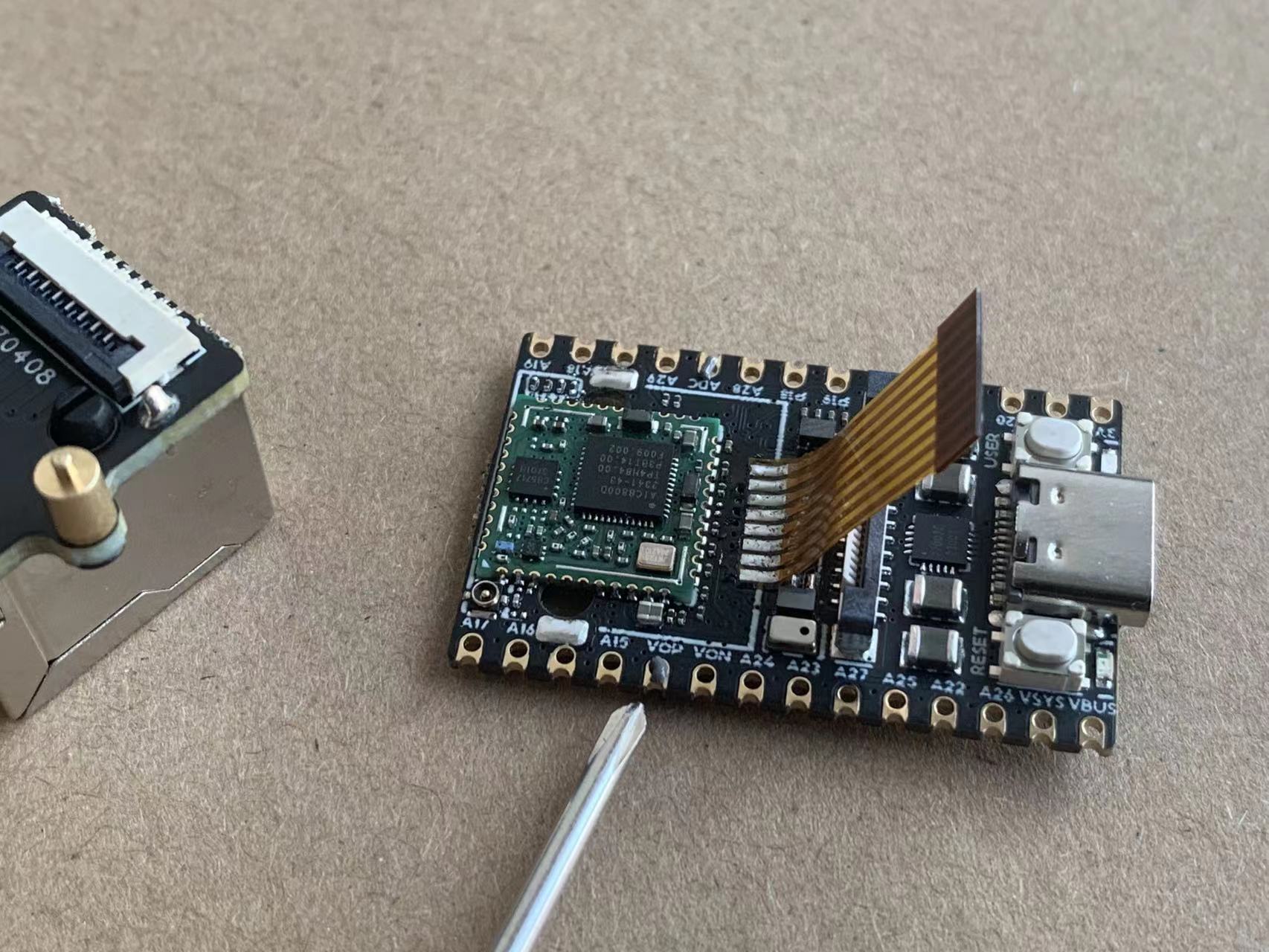
- Soldering the Ribbon Cable
- Solder the ribbon cable following the direction shown in the diagram below.
Use a Multimeter to Test for Continuity
●Securing the Standoffs
- To avoid burns while soldering the standoffs, you can first screw them onto the Ethernet module.
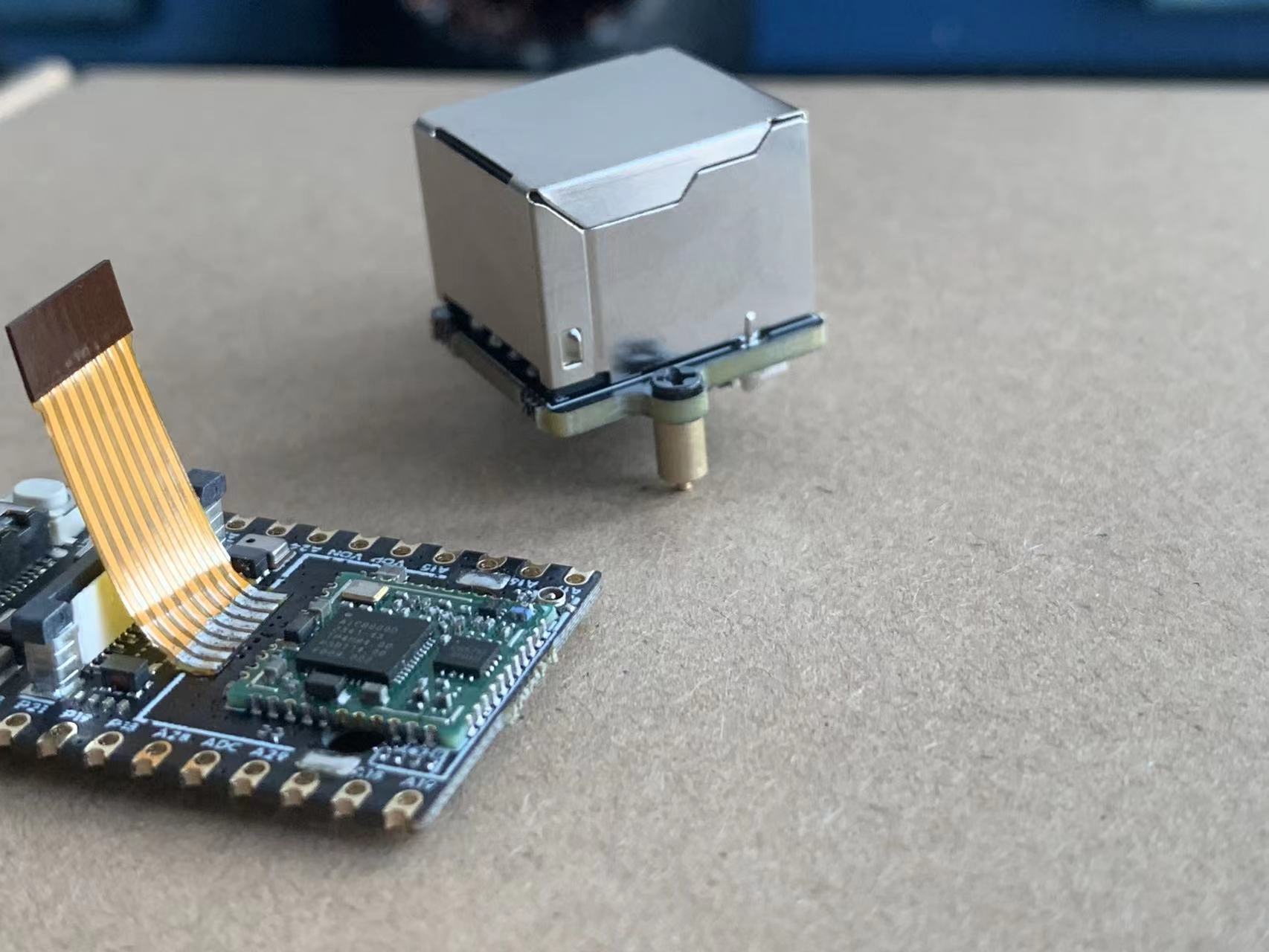
- Insert the standoff into the fifth pad. It is advisable to apply solder paste to the pad beforehand to enhance the stability of the standoff after soldering.
- Use a soldering iron from the bottom side to solder.
Assembly
- Insert the ribbon cable into the FPC connector of the Ethernet module and secure it.
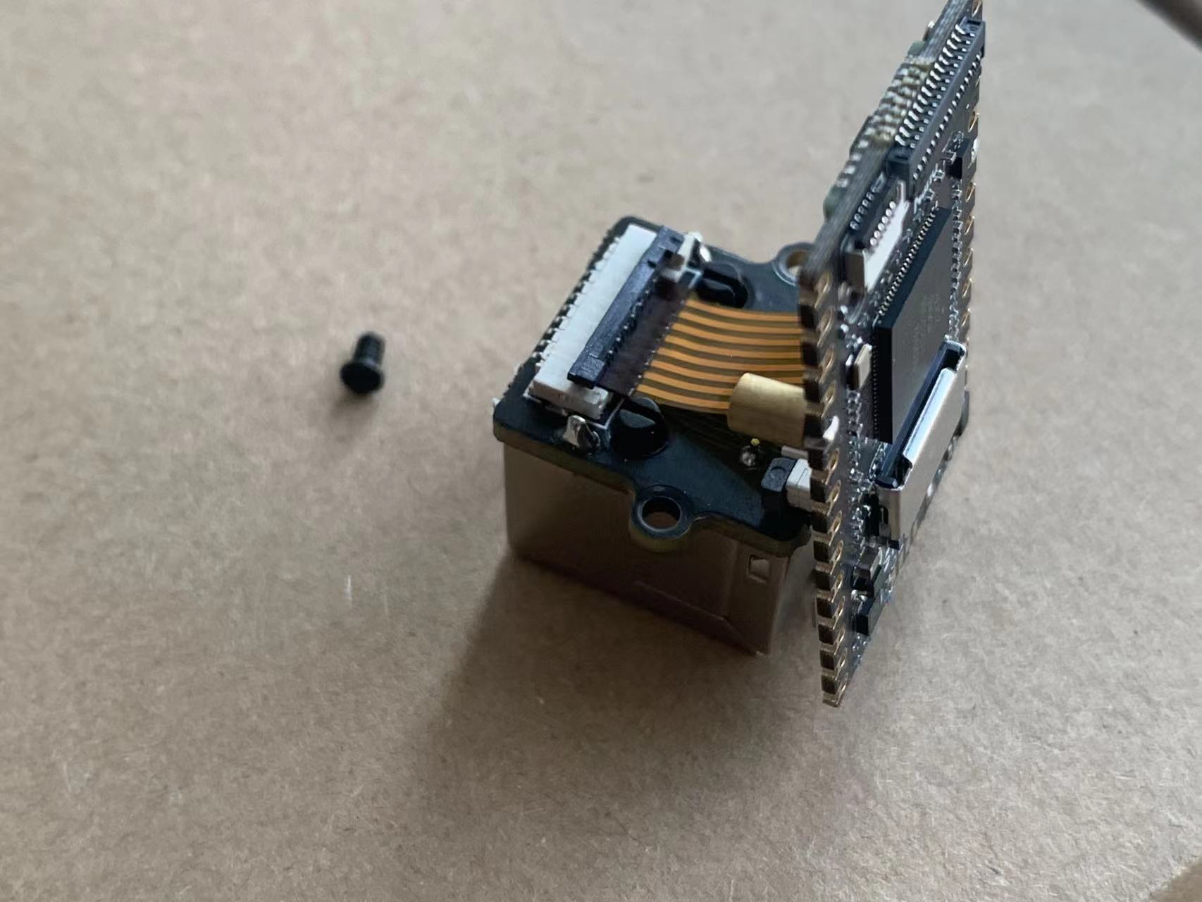
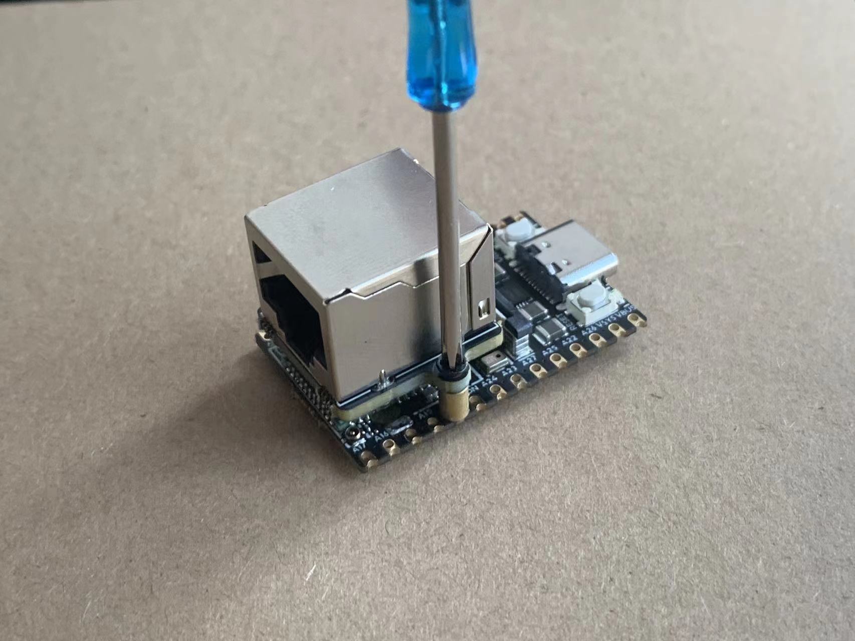
- Secure the Ethernet module to the standoffs using screws.
Installing the Camera
- Securing the Standoffs
- Similar to the method mentioned above: first, screw the standoffs and screws onto the camera module.
- Insert the standoff into the fifth pad. To enhance the stability of the standoff after soldering, it is recommended to apply solder paste to the pad beforehand.
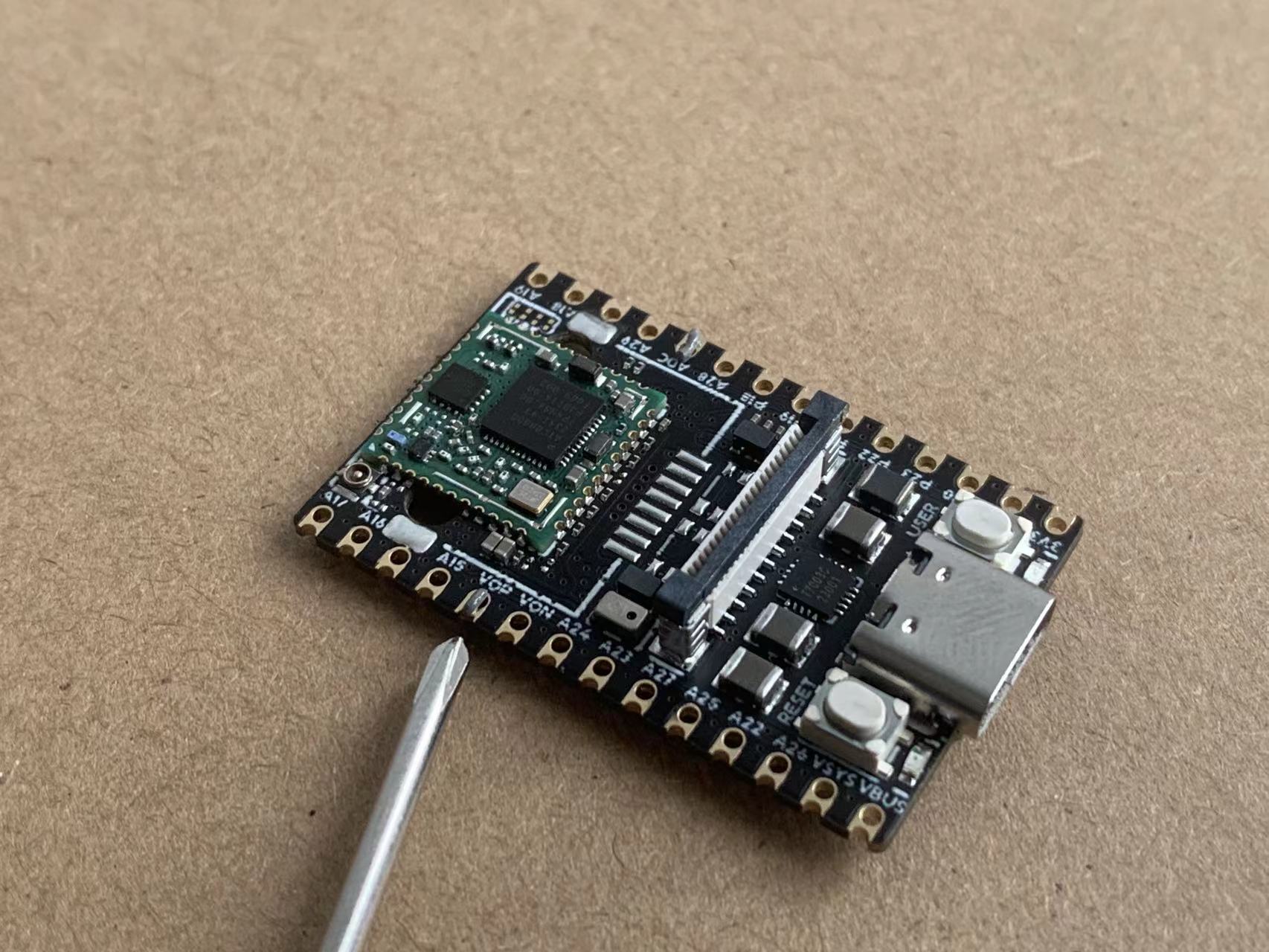
- Solder from the bottom side using a soldering iron.
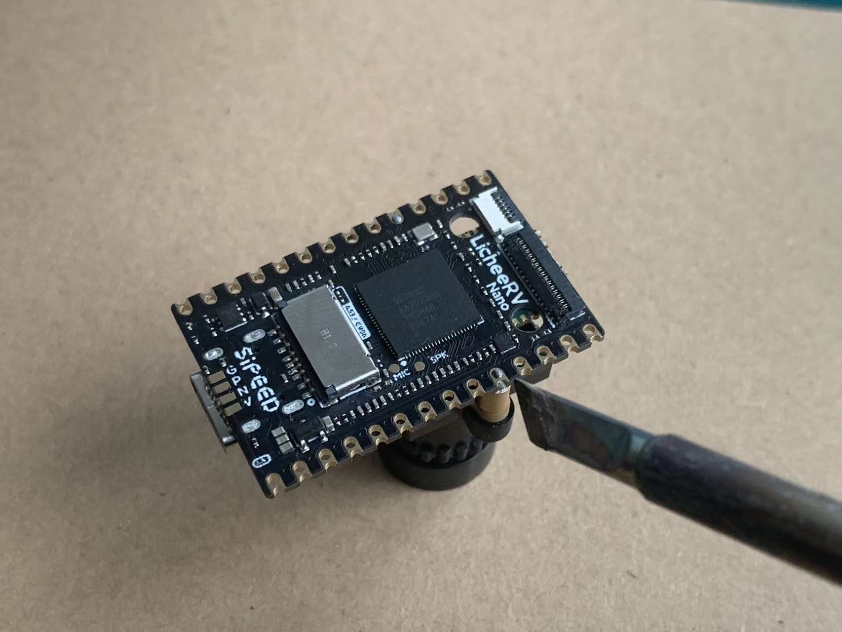
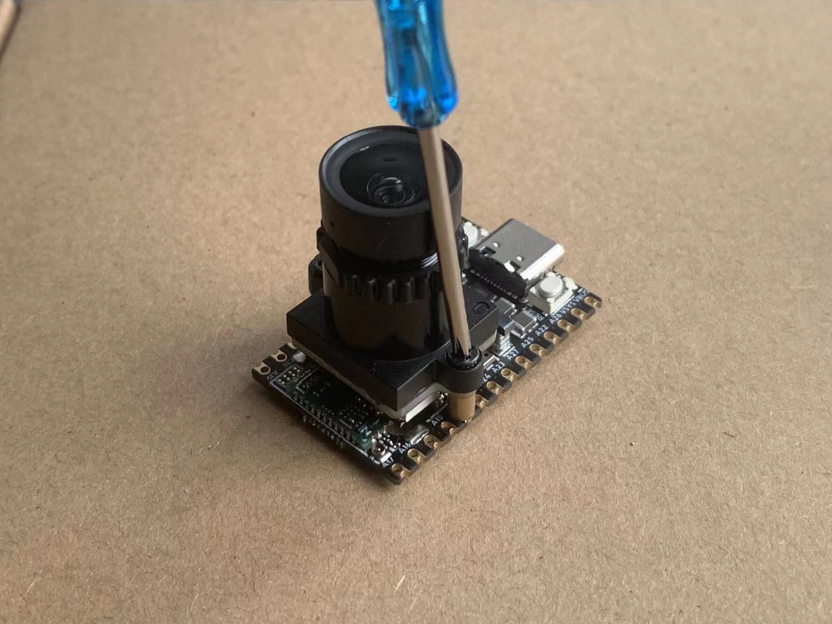
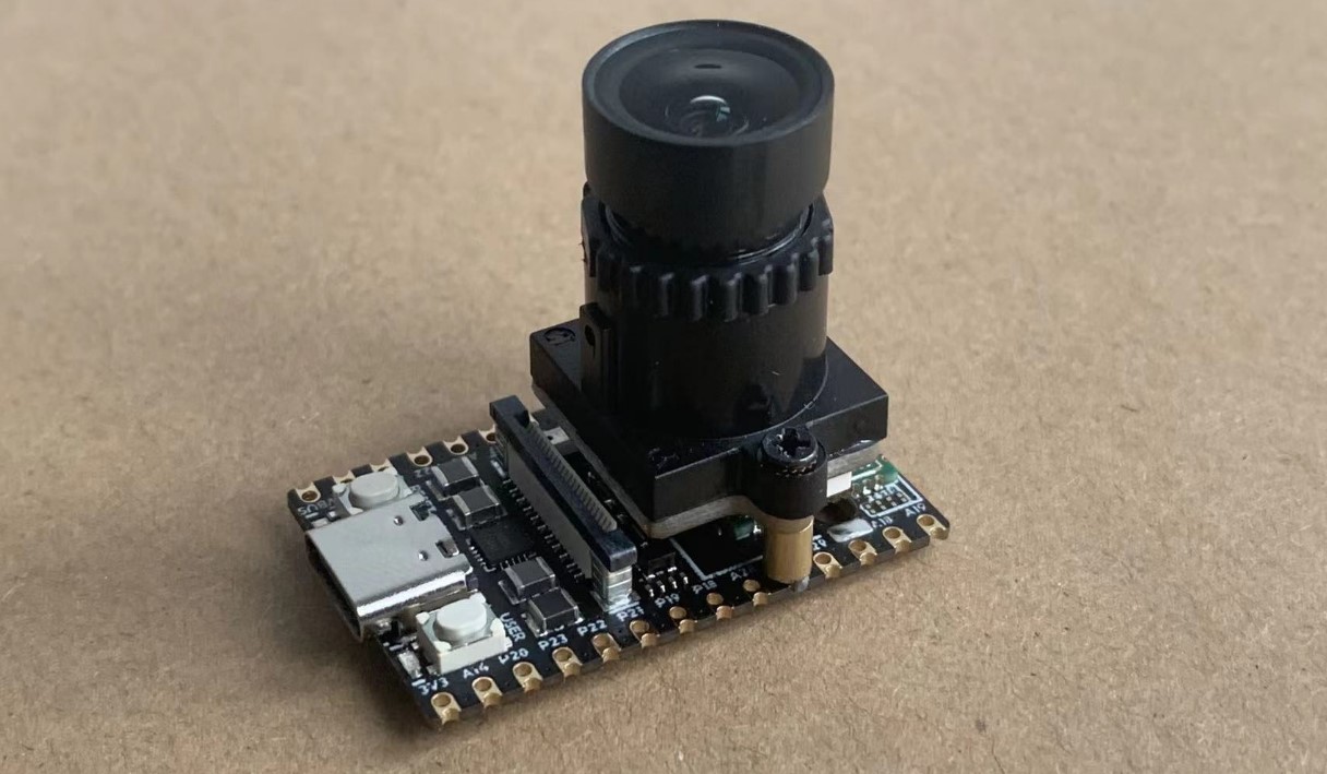
Assembly
- Connect the camera ribbon cable as shown in the diagram below.
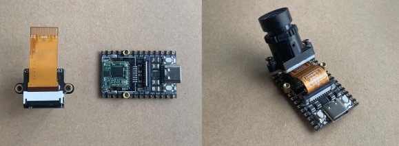
- Secure with screws.