

 English
Peripheral
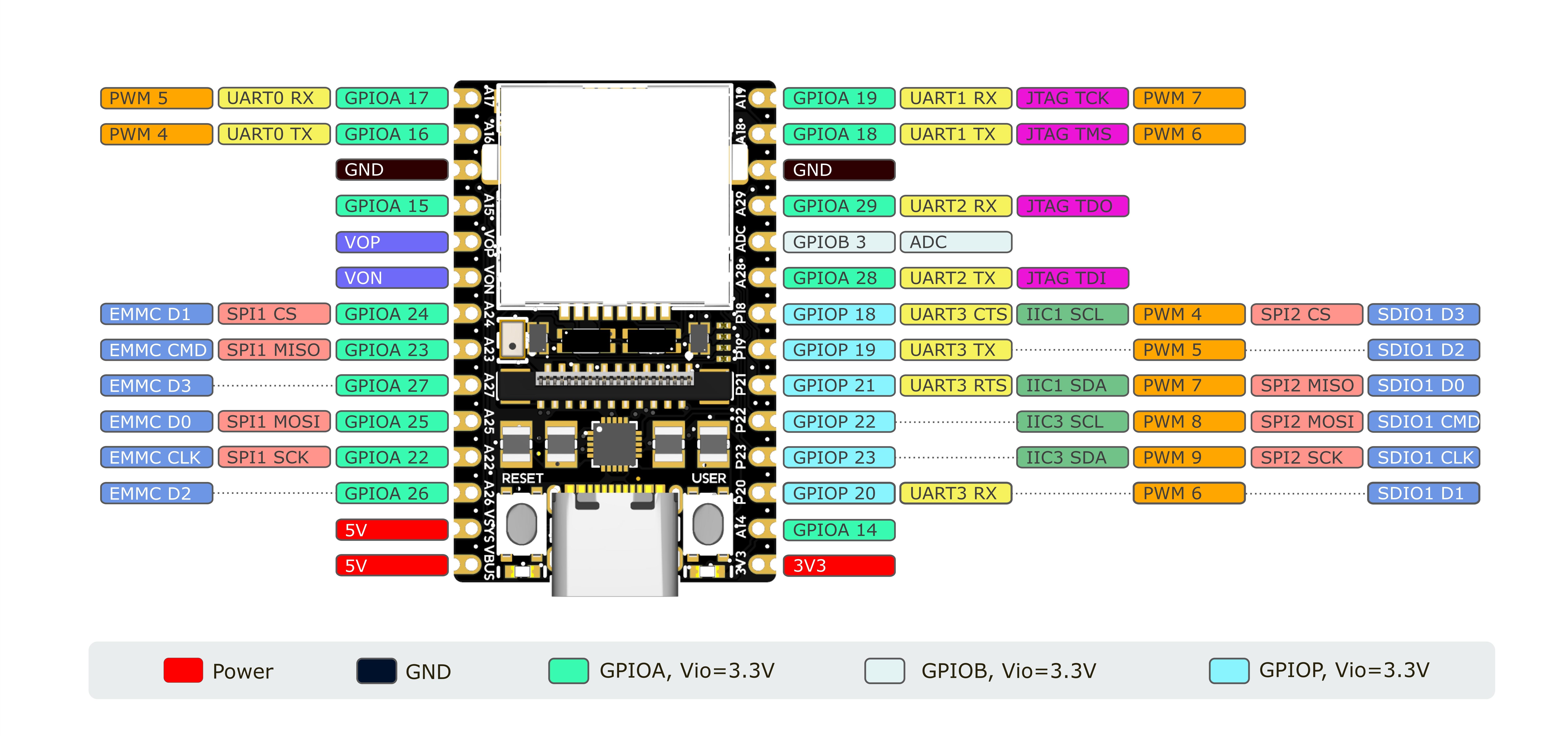
Pinout
Connecting to the Board
UART0
Connect the UART serial port to the GND, A16 (TX), and A17 (RX) of the board.
Then use terminal software to connect to the serial port, with a baud rate of 115200.
UART0 is also brought out on SBU1/2 on the USB interface. You can use the USB Type-C adapter to bring out RX0 and TX0.
Disable UART0 output log
First, transfer the output of the user space to another tty device:
#include <stdlib.h>
#include <unistd.h>
#include <sys/ioctl.h>
#include <fcntl.h>

int main(int argc, char *argv[]) {
        int fd;
        if (argc < 2) {
                fprintf(stderr, "usage: %s /dev/ttyX\n", argv[0]);
                exit(EXIT_FAILURE);
        }
        fd = open(argv[1], O_RDWR);
        if (fd < 0) {
                perror("open");
                exit(EXIT_FAILURE);
        }
        ioctl(fd, TIOCCONS);
        close(fd);
        exit(EXIT_SUCCESS);
}
riscv64-unknown-linux-gcc tioccons.c -o tioccons
./tioccons /dev/tty2 # Transfer /dev/console to tty2
Then set the kernel log level:
echo 0 > /proc/sys/kernel/printk
Test method:
echo userspace > /dev/console
echo kernel > /dev/kmsg
Another way is to add the following content to /boot/uEnv.txt to switch the console to another tty:
consoledev=/dev/ttyX
UART1 UART2 UART3
By default, the pins of UART1 and UART2 are used to connect to the UART Bluetooth chip:
mmio_write_32(0x03001070, 0x1); // GPIOA 28 UART1 TX
mmio_write_32(0x03001074, 0x1); // GPIOA 29 UART1 RX
mmio_write_32(0x03001068, 0x4); // GPIOA 18 UART1 CTS
mmio_write_32(0x03001064, 0x4); // GPIOA 19 UART1 RTS
If you only want to use UART1, you don't need to change PINMUX, just connect GPIOA28 GPIOA29.
If you want to use the functions of UART1 and UART2 at the same time, you need to write to the register to set the PINMUX of the pin:
In Linux user space, you can use the devmem tool to write registers.
shell:
devmem 0x03001070 32 0x2 # GPIOA 28 UART2 TX
devmem 0x03001074 32 0x2 # GPIOA 29 UART2 RX
devmem 0x03001068 32 0x6 # GPIOA 18 UART1 RX
devmem 0x03001064 32 0x6 # GPIOA 19 UART1 TX
The UART3 pins are multiplexed as SDIO by default:
mmio_write_32(0x030010D0, 0x0); // D3
mmio_write_32(0x030010D4, 0x0); // D2
mmio_write_32(0x030010D8, 0x0); // D1
mmio_write_32(0x030010DC, 0x0); // D0
mmio_write_32(0x030010E0, 0x0); // CMD
mmio_write_32(0x030010E4, 0x0); // CLK
If you want to use the UART3 function, you need to write to the register to set the PINMUX of the pin:
In Linux user space, you can use the devmem tool to write registers.
shell:
devmem 0x030010D0 32 0x5 # GPIOP 18 UART3 CTS
devmem 0x030010D4 32 0x5 # GPIOP 19 UART3 TX
devmem 0x030010D8 32 0x5 # GPIOP 20 UART3 RX
devmem 0x030010DC 32 0x5 # GPIOP 21 UART3 RTS
Serial port usage in a Linux system:
C:
/* TODO */
shell:
stty -F /dev/ttyS1 115200 # Set the UART1 baud rate to 115200
stty -F /dev/ttyS1 raw    # Set tty to RAW mode
echo -n UUU > /dev/ttyS1 # Send UUU(0x55 0x55 0x55)
hexdump -C /dev/ttyS1     # Display the received data in HEX format
USB CDC ACM Serial Port
When the board's USB Type-C port is connected to a computer, it will provide a USB CDC ACM serial port device (provided by Linux gadget).
Linux:
# Replace /dev/ttyACMX with the specific device, depending on your computer
picocom -b 9600 /dev/ttyACMX
Windows:
Press Win + R, enter devmgmt.msc, and press Enter.
Find the new device's serial port number under the serial port devices.
Then use PuTTY or HyperTerminal to connect.
USB RNDIS Network Port
When the board's USB Type-C port is connected to a computer, it will provide a USB RNDIS network card device (provided by Linux gadget).
The PC will automatically obtain an address using DHCP.
Replace the last digit of the automatically obtained IPv4 address with 1 to get the board's IPv4 address:
10.44.55.66 PC's IPv4 address
10.44.55.1  Board's IPv4 address
Then use ssh to connect: ssh root@board's IP address
Username: root
Password: root
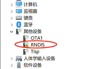
On Windows system, some configurations need to be made.
Open Device Manager and find the following option:
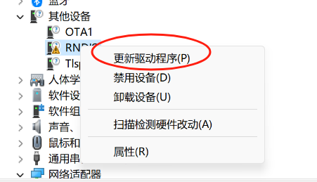
Select "Update driver":
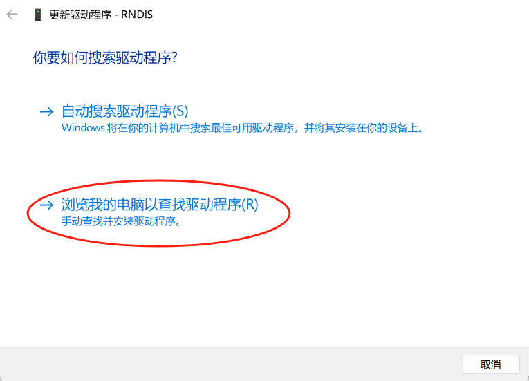
Select "Browse my computer for driver software":
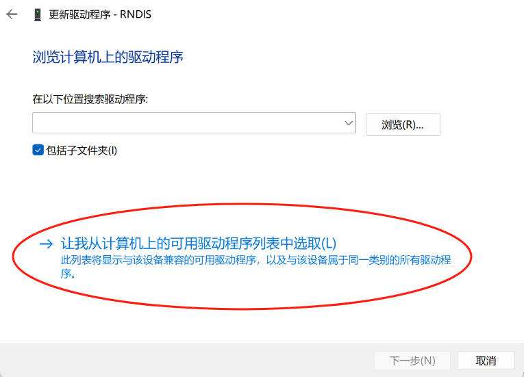
Select "Let me pick from a list of available drivers on my computer":
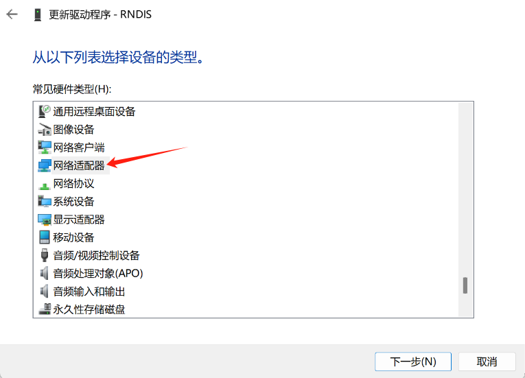
In the device type list, select "Network adapters":
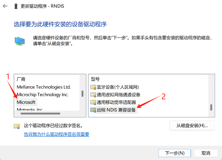
For manufacturer, select "Microsoft"; for model, select "Remote NDIS Compatible Device":
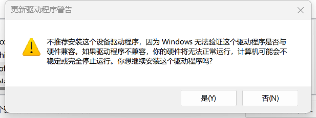
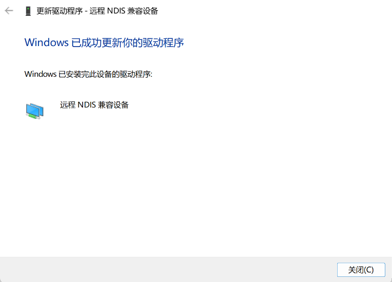
If this warning pops up, please click "OK":
After the update is successful, it will show as follows:
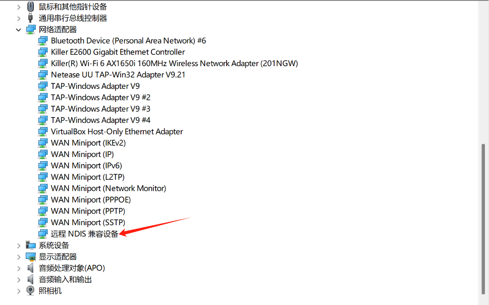
Then you can find the "Remote NDIS Compatible Device" item under the Network adapters list in Device Manager:
Ethernet Connection
Connect the Ethernet cable to the board; the board will automatically obtain an address using DHCP upon boot.
The board's image defaults to enabling the MDNS service.
Use the command:
avahi-browse -art | grep lpirvnano
to list devices in the broadcast domain with lpirvnano in their domain names.
Then use:
ssh root@lpirvnano-XXXX.local
to connect to the board.
Disabling the Boot Demo of the Image
# Clear rc.local
echo '#!/bin/sh' > /etc/rc.local
# Reboot
reboot
Audio
The LicheeRV Nano supports recording and playback. Standard ALSA tools can be used for recording, playback, and other operations.
Recording
First, set the microphone volume, range: 0-24
amixer -Dhw:0 cset name='ADC Capture Volume' 24
After setting, start recording:
arecord -Dhw:0,0 -d 3 -r 48000 -f S16_LE -t wav test.wav & > /dev/null &
Playback
./aplay -D hw:1,0 -f S16_LE test.wav
I2C
I2C1 and I2C3 are brought out on the pin header, and devices can be connected to them.
Before using, you need to correctly set the PINMUX:
# I2C1
devmem 0x030010D0 32 0x2
devmem 0x030010DC 32 0x2
# I2C3
devmem 0x030010E4 32 0x2
devmem 0x030010E0 32 0x2
Then you can use i2c-tools to operate the i2c peripherals. The image is already pre-installed.
ADC
An ADC channel is brought out on the pin header, using ADC1.
First, select the ADC channel, here taking ADC1 as an example:
echo 1 > /sys/class/cvi-saradc/cvi-saradc0/device/cv_saradc
Read the value of ADC1:
cat /sys/class/cvi-saradc/cvi-saradc0/device/cv_saradc
LCD
Connect the screen's ribbon cable to the board's MIPI interface, paying attention to the wire order.
Create or edit the uEnv.txt file in the first partition of the sdcard, add or modify the panel field:
Note: The image will have the first partition already mounted in the /boot directory and can be used directly in the terminal:
cd /boot
touch uEnv.txt
vi uEnv.txt
# Use 'i' to enter edit
# Use 'Esc',':wq' to save and quit
7-inch screen:
panel=zct2133v1
5-inch screen:
panel=st7701_dxq5d0019b480854
3-inch screen:
panel=st7701_d300fpc9307a
2.3-inch screen:
panel=st7701_hd228001c31
If you want to use the framebuffer function, create a file named fb in the first partition of the sd card:
touch /boot/fb
Then load the driver:
/etc/init.d/S04fb start
Adjusting the Backlight Brightness:
echo 0 > /sys/class/pwm/pwmchip8/pwm2/enable
echo 5000 > /sys/class/pwm/pwmchip8/pwm2/duty_cycle # 50%
echo 1 > /sys/class/pwm/pwmchip8/pwm2/enable

# some example:
#echo 2000 > /sys/class/pwm/pwmchip8/pwm2/duty_cycle # 20%
#echo 4000 > /sys/class/pwm/pwmchip8/pwm2/duty_cycle # 40%
#echo 7000 > /sys/class/pwm/pwmchip8/pwm2/duty_cycle # 70%
#echo 9000 > /sys/class/pwm/pwmchip8/pwm2/duty_cycle # 90%
Touch Screen
Connect the touchscreen ribbon to the board's touchscreen interface, paying attention to the wire sequence.
Then execute:
/opt/touch.sh # Load the touchscreen driver
Followed by:
echo 2 | evtest
Touching the screen will display specific coordinates in the terminal.
For reading coordinates and touch events, refer to the input section in /opt/src/vendortest.
WIFI
Install the antenna onto the WIFI module's antenna connector.
Then write the AP's SSID and password into the /etc/wpa_supplicant.conf file:
network={
        ssid="ssid"
        psk="password"
}
After that, execute:
/opt/wifi.sh
To verify if the network is available:
ping your gateway address
If available, you can add it to the boot script:
echo '/opt/wifi.sh' >> /etc/rc.local
Camera
Install the camera onto the camera mount, paying attention to the wire sequence.
Then execute:
/mnt/system/usr/bin/sample_vio 6 # Real-time display of camera images on the screen
# Type 255 to exit the program
/mnt/system/usr/bin/sensor_test # Camera test program that can be used to dump single YUV images.
When using the 70405 (beta) boards:
touch /boot/alpha # Beta version
# rm /boot/alpha  # Official version
cd /mnt/data
cp sensor_cfg.ini.alpha sensor_cfg.ini   # Beta version
# cp sensor_cfg.ini.beta sensor_cfg.ini  # Official version
Button
To view button events, use the command:
echo 1 | evtest
Then press the USER button, and you will see the corresponding event report in the terminal.
HelloWorld
For information on compiling programs using the vendor's toolchain, visit:
