

 English
Tang Mega 60K Dock
Update history
| Date | Version | Author | Update content |
|---|---|---|---|
| 2025-09-25 | v0.31 | Serika |
|
| 2025-01-24 | v0.3 | Serika |
|
| 2024-09-26 | v0.2 | Serika |
|
| 2024-06-26 | v0.1 | Serika |
|
Overview
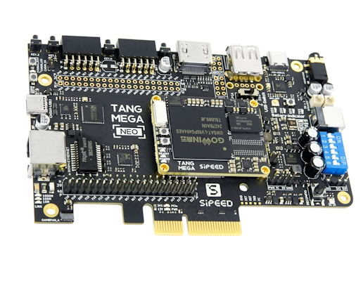
Tang Mega 60K uses the 22nm process GW5AT-LV60P484A FPGA chip with 59904 lookup table units and 118 DSP units. It contains four high-speed transceivers with speeds ranging from 270Mbps to 8.8Gbps, which is suitable for transmitting data on high-speed ports such as PCIe. In addition, the chip contains hard-core PCIe and MIPI D-PHY controllers, which consume better resources and get better performance when using PCIe. It is suitable for high-speed communication, protocol conversion, high-performance computing and other occasions.
The 60K Dock and 138K Dock share a set of dockboards(TANG MEGA NEO), so the peripherals of the two are exactly the same. Compared with the 138K Dock, the 60K Dock has fewer logic resources and a lower price, and includes a MIPI D-PHY transceiver. This not only further reduces the cost of high-speed communication, but also brings better compatibility for image processing system integration.
- aliexpress purchase link: Click me
Board Features
Medium capacity LUT4
512MiB DDR3 memory
PCIe 2.0 x 1*
USB3.0 x 1(5Gbps)
MIPI C-PHY & D-PHY RX/TX
HDMI TX/RX x 1
Gigabit Ethernet x 1
Onboard 3.7V Li-on battery(1-Series) charge/discharge management
Note: Since the pinouts of the SERDES parts of
GW5AT-LV60andGW5AST-LV138are not exactly the same, the Dock board was originally designed forGW5AST-LV138. Therefore, forGW5AT-LV60, although the PCIe AIC gold finger has fanout all SERDES lanes, because lanes 1 and 3 are swapped on theGW5AT-LV60, PCIe can only work in x1 mode at present.This problem may be fixed in the future with GOWIN software updates.
Product Appearance
Block Diagram
TBD
Hardware Parameters
SOM Board Parameters
| Item | Parameter | Supplement | ||||||||||||||||||||||||||||||||||||
|---|---|---|---|---|---|---|---|---|---|---|---|---|---|---|---|---|---|---|---|---|---|---|---|---|---|---|---|---|---|---|---|---|---|---|---|---|---|---|
| FPGA Chip | GW5AT-LV60PG484AC1/I0 |
|
||||||||||||||||||||||||||||||||||||
| Memory | 4Gb DDR3 | 512MB x 1 | ||||||||||||||||||||||||||||||||||||
| Flash | 64Mbits Flash x 1 | See How to Burn to Flash | ||||||||||||||||||||||||||||||||||||
| Debug Interface | JTAG + UART | JST SH1.0 8-Pins CONN. | ||||||||||||||||||||||||||||||||||||
| Overall Package | 35mm x 45mm Size | BTB CONN. Connects the SOM and the Dock Board |
Dock board Parameters
| Item | Quantity | Remarks |
|---|---|---|
| LEDs | 4+8 | 4x Battery-Indicator+ 8x PMOD_LED |
| WS2812 | 1 | The WS2812 & aRGB strip CONN. share the same pin |
| Buttons | 3+1 | 3x User-KEY + 1x Reconfig-KEY |
| PCIe | 1 | 4-lane @ 5Gbps, but only 1-lane mode right now |
| USB3 | 1 | CH569 16bit HSPI, SuperSpeed @ 5Gbps |
| Ethernet | 1 | 1000Mbps Ethernet |
| DVI(HDMI) | 1 | DVI supports both RX and TX |
| PMOD | 2 | Multiplexed with the DVP CONN. & 2x20P header at the top of the Dock board |
| ADC | 2 | 2x differential input channels |
| DVP Interface | 1 | Multiplexed with the PMOD & 2x20P header at the top of the Dock board |
| RGB Interface | 1 | Supports RGB888 screen |
| MIC ARRAY Interface | 1 | Supports Sipeed 6+1 microphone array |
| SD Slot | 1 | 1-bit SDIO/MMC or SPI mode |
| BATT CONN. | 1 | Supports 3.7V li-on battery, with built-in charge management |
| PWM FAN CONN. | 1 | Supports PWM fan with TACHO |
| Speaker CONN. | 2 | Support stereo output, 2x 3W Speaker |
| 3.5mm Headphone CONN. | 1 | Supports stereo output, without Mic |
| MS5351 | 1 | Provides RefClk for Serdes; control output via onboard UART |
| USB JTAG & UART | 1 | Supports FPGA programming and provides UART function |
| 2x20P headers | 2 | 2x20P header at the top of the Dock board multiplexed with the PMOD & DVP CONN. |
| Power button | 1 | Press and hold for 2 seconds to toggle power state |
| 12V DC | 1 | DC5521 |
Hardware Resources
- ~~ Specification~~
- Schematics
- PCB BOM
- Dimension Diagram
- 3D Model
- Some Chip Manuals
- All PIN Constraints
Getting Started
Note that 60K is currently supported by the educational version. You need to download the educational IDE version V1.9.11.03 or later. The commercial IDE requires V1.9.10.03 or later.
To download the bitstream to flash memory, we recommend using exFlash Erase, Program through GAO-Bridge 5A mode (V1.9.10.03 or later) or exFlash Erase, Program through GAO-Bridge Arora V (V1.9.12 or later).
We recommend using the standalone 1.9.12 SP1 Programmer (also known as Yunyuan Programmer), which can be found on the Yunyuan Software Commercial Version page. This standalone programmer offers better compatibility.
If you need to use the commercial IDE, you can apply for a license on the Gaoyun official website or use the online license service provided by Sipeed. Select Floating License in the IDE and fill in the following information:
---Server 01---
ip: 106.55.34.119
port: 10559
if the ip not work, try use "gowinlic.sipeed.com" domain's IP.
Install IDE Click me
Example code github
Other Learning Resources
- Free online tutorial: Verilog Tutorial (Learn Verilog)
- Free online FPGA tutorial: Verilog (English website)
- Verilog practice website: HDLBits (English website)
- Online Gowin Semiconductor reference video tutorials: Click here
Communication Methods
- Reddit : reddit.com/r/GowinFPGA/
- Telegram : t.me/sipeed
- Discussion forum: maixhub.com/discussion
- QQ discussion group: 834585530
- Leave a message directly below this page
- GotoGitHub project pageand submit issues
- Business email : support@sipeed.com
Precautions
| Item | Precautions |
|---|---|
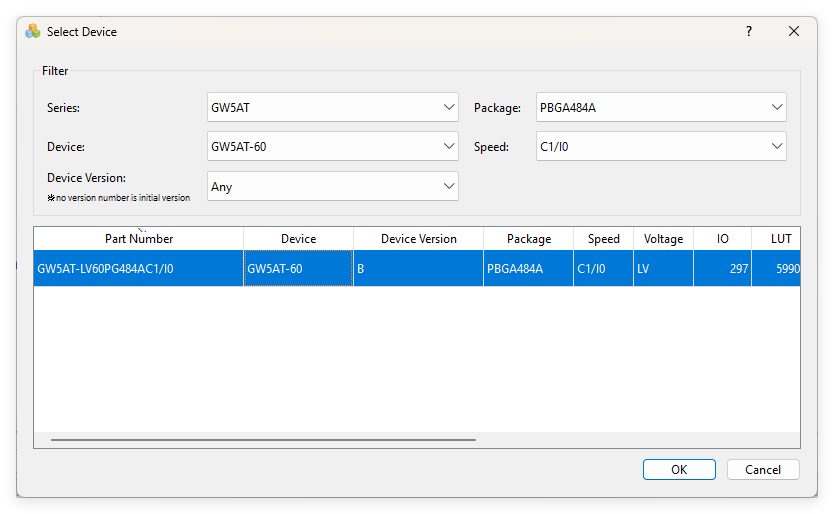
| Chip Model | The specific model of the FPGA chip used by Tang Mega 60K is GW5AT-LV60PG484A Please select the package model PBG484A & Device Version: B in the IDE. |
| Static Electricity | Please avoid static electricity hitting the PCBA; release the static electricity from your hands before touching the PCBA. |
| Tolerance Voltage | When using GPIO pin headers for external communication, ensure that the IO voltage is 3.3V. Excessive voltage will permanently damage the PCBA. |
| FPC Socket | When connecting the FPC soft cable, please ensure that the cable is completely and correctly inserted into the socket without any deviation. |
| PCIE Gold Finger | When testing the PCIE gold finger, ensure that both the host and the board are in the off or unpowered state to avoid short-circuiting the gold finger due to displacement during the insertion process. |
| Plug and Unplug | Please completely power off before plugging and unplugging. |
| Avoid Short Circuit | Please avoid any liquid or metal touching the solder pads of the components on the PCBA during the power-on process, otherwise it may cause a short circuit and burn the PCBA. |
Contact
Tang Mega 60K can meet different needs of customers in various scenarios. For technical support and business cooperation, please contact support@sipeed.com
Frequently Asked Questions (FAQs)
The system does not recognize the debugger
- Try connecting directly to the computer instead of through a USB HUB.
- Try using a better quality USB cable.
- Try another computer to rule out the computer being the problem.
- Try update to the latest firmware and try again.
The UART of the onboard debugger cannot be used
- Try reinstall FTDI drivers.
- IF the actual baudrate is always four times the set baudrate or the UART continuously outputs garbled characters. try update to the latest firmware and try again.
OpenFPGAloader not work
- Try update to the latest firmware and try again.
How to update the firmware for the onboard debugger
- See Update the debugger for details.
After powering on the board, only four indicator lights on the dockboard are on, the SOM indicator light is not on
- Please check if the board’s power has been turned on, press and hold the PWR button (next to the HDMI port) for 2 seconds to turn on the power.
After powering on the board, the Battery-Indicator light on the dcokboard is flashing
- This is normal behavior, usually, the last LED (near the 12V DC connector) is flashing;
- When the board is connected to a 3.7V lithium battery, these LEDs will serve as battery level indicators.
After pressing and holding the PWR button for 2 seconds, all the indicator lights on the dockboard turn off and then light up in sequence
- Check your power supply method, this situation means that the power supply is insufficient;
- Solutions (choose one):
a. Connect both the board’s USB-3.0 and USB-DEBUG for power supply, i.e., dual 5V USB power supply;
b. Connect a 12V DC power supply to the board, if using the USB-C to 12V DC connector from the accessories, a PD power source with 12V output capability is required;
c. Connect a 3.7V lithium battery to power the board, note that the battery voltage must be ≥3.6V and the continuous discharge capacity must be ≥600mA.
IDE cannot find the model GW5AT-LV60PG484A
- The GOWIN IDE version is too old. You must update to the commercial version IDE ≥ 1.9.10.03, or the educational version IDE ≥ 1.9.11.03.
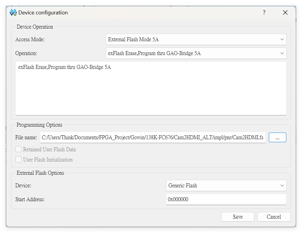
How to burn the bitstream to FLASH
- Setting the Programmer as shown in the figure below:
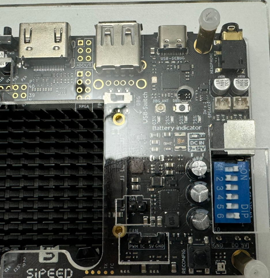
- Check the position of the DIP switch; the correct position is shown in the figure below:
No Response or Undesirable Pin Phenomenon After Burning
- First, ensure that the IDE has selected the correct model GW5AT-LV60PG484AC1/10; every parameter in the figure below MUST be consistent.
- Then, check your code and the corresponding simulation waveforms to meet the requirements. The GAO tools in GOWIN IDE maybe helpful. For more information, please refer to the GOWIN document SUG100(require login).
