

 English
Drive RGB screen
Edit on 2022.04.19
Introduce timing
RGB LCD display protocol is similar to VGA protocol, both have horizon synchronization signal line and vertical synchronization signal line. The main difference is that RGB LCD display protocol transfers by digital signal while VGA protocol transfers by analog signal.
Here we introduce VGA timing.
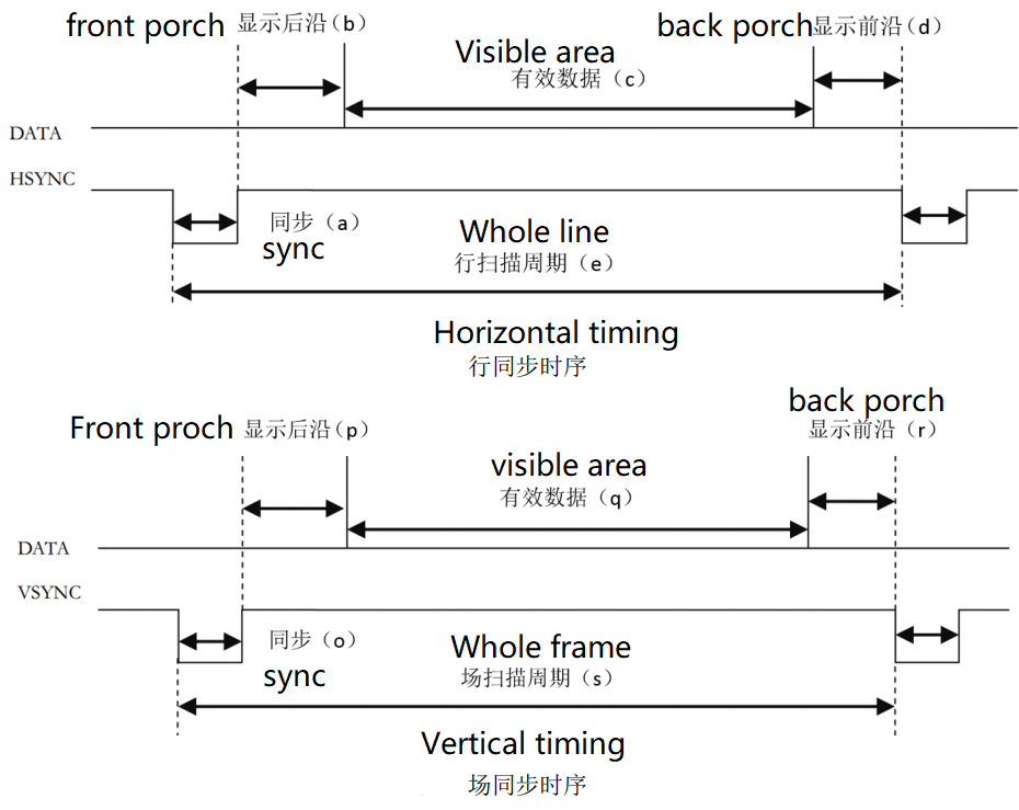
There shows horizon synchronization timing and vertical synchronization timing in the picture above.
From the timing picture, we know both display a horizon of data or display a vertical of data, data transfers during the two synchronization signal pulses.
Each horizon of data contains back porch, visible data (this is normally thought as active data) and front porch.
The visible data is resolution we normally think, while the parameter of back porch and front porch depends on the resolution and frame rate. Its typical parameters can be found in this web. http://www.tinyvga.com/vga-timing
The timing of this 5-inch screen we sell is a bit different, its parameters can be downloaded here. Detail book
For other size screen parameters, they can be downloaded here. Click me
The following picture shows the screenshot about this LCD timing.
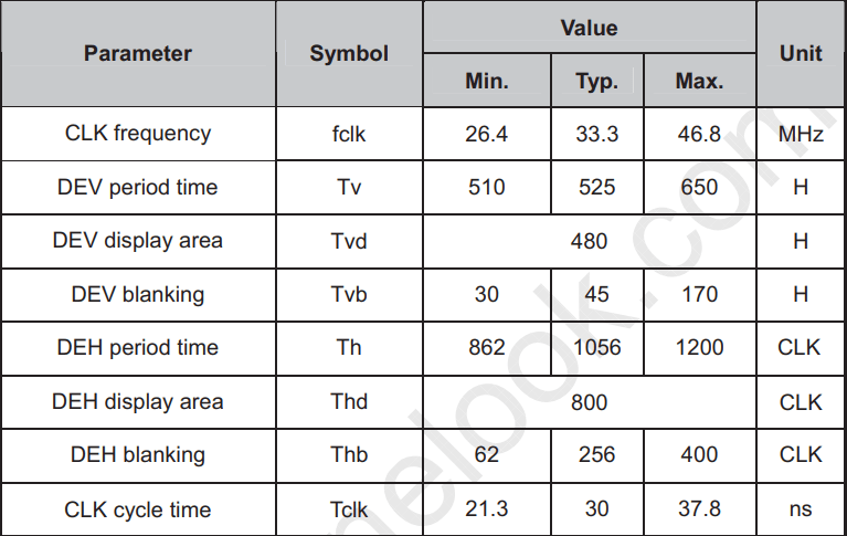
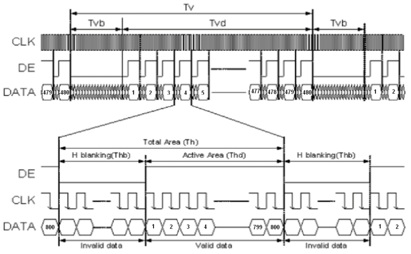
The first picture form shows parameters of the screen and the following picture is its timing.
From its timing picture, we can know we don't need to set front porch time and back porch time, we just need to set blanking time.
Create project
Please refer to this article to see how to create project.
Generate screen clock
- Here we use gowin official IP
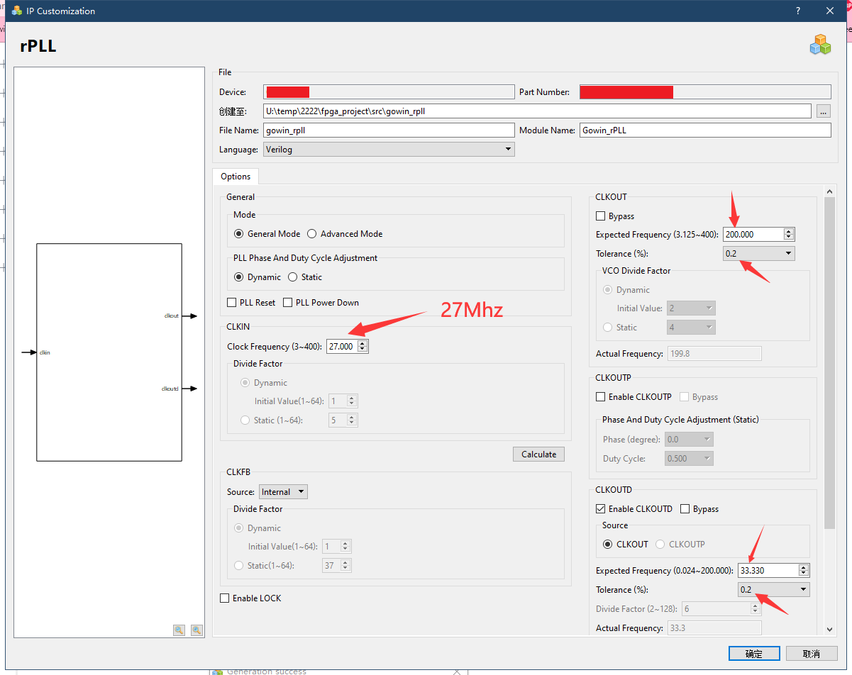
The crystal oscillator onboard is 27MHz, but our screen needs 33.3MHZ clock, so we need to use the corresponding ip core to generate the corresponding clock.
Here we use IP Core Generate which can be find in Tools -> IP Core Generate
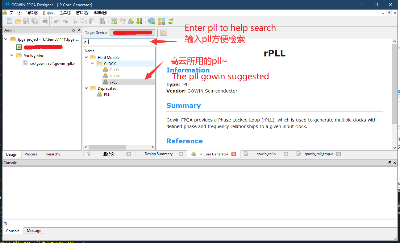
Double click rPLL and select Verilog in the pop-up window language, set CLKIN 27MHz, CLKOUTD is 33.00MHz. Also config the tolerance.
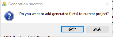
After click OK it asks whether add it to current project, here we choose yes.
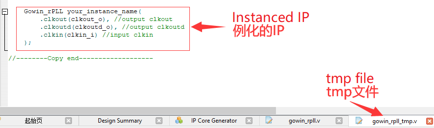
Then a tmp file will appear, we can use it to generate the ip, like what is shown below.
Screen driver
- To start this we should create a verilog file first
Port definition
First define ports which are needed to drive screen
module VGAMod
(
    input                   CLK,
    input                   nRST,

    input                   PixelClk,

    output                  LCD_DE,
    output                  LCD_HSYNC,
    output                  LCD_VSYNC,

    output          [4:0]   LCD_B,
    output          [5:0]   LCD_G,
    output          [4:0]   LCD_R
);
We use RGB565 driver mode.
Timing constants
Then we define the constants according to the timing form picture
localparam      V_BackPorch = 16'd6; //0 or 45
localparam      V_Pluse 	= 16'd5;
localparam      HightPixel  = 16'd480;
localparam      V_FrontPorch= 16'd62; //45 or 0

localparam      H_BackPorch = 16'd182;
localparam      H_Pluse 	= 16'd1;
localparam      WidthPixel  = 16'd800;
localparam      H_FrontPorch= 16'd210;

localparam      PixelForHS  =   WidthPixel + H_BackPorch + H_FrontPorch;
localparam      LineForVS   =   HightPixel + V_BackPorch + V_FrontPorch;
First we define front porch, back porch and valid pixel data.
As for the front porch timing and back porch timing which have been mentioned earlier, it can be combined into an erasing time, that is, one can be set to 0, and the other can be set to the erasing time. Anyway, the front porch timing and back porch timing can be added up to meet the timing requirements in the table is ok.
Define variables
- Define some variables helps us to meet timing requirment
reg [15:0] LineCount;
reg [15:0] PixelCount;

reg	[9:0]  Data_R;
reg	[9:0]  Data_G;
reg	[9:0]  Data_B;
Synchronization signals
This code generates synchronization signals. It should be noted that the synchronization signals of this screen enabled by negative polarity
    always @(  posedge PixelClk or negedge nRST  )begin
        if( !nRST ) begin
            LineCount       <=  16'b0;
            PixelCount      <=  16'b0;
            end
        else if(  PixelCount  ==  PixelForHS ) begin
            PixelCount      <=  16'b0;
            LineCount       <=  LineCount + 1'b1;
            end
        else if(  LineCount  == LineForVS  ) begin
            LineCount       <=  16'b0;
            PixelCount      <=  16'b0;
            end
        else
            PixelCount      <=  PixelCount + 1'b1;
    end

   always @(  posedge PixelClk or negedge nRST  )begin
        if( !nRST ) begin
    		Data_R <= 9'b0;
    		Data_G <= 9'b0;
    		Data_B <= 9'b0;
            end
        else begin
    		end
    end

//Here note the negative polarity of HSYNC and VSYNC
assign  LCD_HSYNC = (( PixelCount >= H_Pluse)&&( PixelCount <= (PixelForHS-H_FrontPorch))) ? 1'b0 : 1'b1;
assign  LCD_VSYNC = ((( LineCount  >= V_Pluse )&&( LineCount  <= (LineForVS-0) )) ) ? 1'b0 : 1'b1;
Enable signal
- This code decides whether display image.
This driver needs a port which is set to 1 when the 800*480 data of the image is valid to enable display.
assign  LCD_DE = (  ( PixelCount >= H_BackPorch )&&
                    ( PixelCount <= PixelForHS-H_FrontPorch ) &&
                    ( LineCount >= V_BackPorch ) &&
                    ( LineCount <= LineForVS-V_FrontPorch-1 ))  ? 1'b1 : 1'b0;
                    //It will shake if there not minus one
Test color bars
- This code generates color bars to test LCD
    localparam          Colorbar_width   =   WidthPixel / 16;

    assign  LCD_R     = ( PixelCount < ( H_BackPorch +  Colorbar_width * 0  )) ? 5'b00000 :
                        ( PixelCount < ( H_BackPorch +  Colorbar_width * 1  )) ? 5'b00001 :
                        ( PixelCount < ( H_BackPorch +  Colorbar_width * 2  )) ? 5'b00010 :
                        ( PixelCount < ( H_BackPorch +  Colorbar_width * 3  )) ? 5'b00100 :
                        ( PixelCount < ( H_BackPorch +  Colorbar_width * 4  )) ? 5'b01000 :
                        ( PixelCount < ( H_BackPorch +  Colorbar_width * 5  )) ? 5'b10000 :  5'b00000;

    assign  LCD_G    =  ( PixelCount < ( H_BackPorch +  Colorbar_width * 6  )) ? 6'b000001:
                        ( PixelCount < ( H_BackPorch +  Colorbar_width * 7  )) ? 6'b000010:
                        ( PixelCount < ( H_BackPorch +  Colorbar_width * 8  )) ? 6'b000100:
                        ( PixelCount < ( H_BackPorch +  Colorbar_width * 9  )) ? 6'b001000:
                        ( PixelCount < ( H_BackPorch +  Colorbar_width * 10 )) ? 6'b010000:
                        ( PixelCount < ( H_BackPorch +  Colorbar_width * 11 )) ? 6'b100000:  6'b000000;

    assign  LCD_B    =  ( PixelCount < ( H_BackPorch +  Colorbar_width * 12 )) ? 5'b00001 :
                        ( PixelCount < ( H_BackPorch +  Colorbar_width * 13 )) ? 5'b00010 :
                        ( PixelCount < ( H_BackPorch +  Colorbar_width * 14 )) ? 5'b00100 :
                        ( PixelCount < ( H_BackPorch +  Colorbar_width * 15 )) ? 5'b01000 :
                        ( PixelCount < ( H_BackPorch +  Colorbar_width * 16 )) ? 5'b10000 :  5'b00000;
Do not forget to add endmodule in the end of the driver file
Up to now we have finished the driver module.
Instantiated in the top
- New a verilog file
- Just copy the content below and save it is ok
module TOP //Name TOP module
(
    input			nRST,
    input           XTAL_IN,

    output			LCD_CLK,
    output			LCD_HYNC,
    output			LCD_SYNC,
    output			LCD_DEN,
    output	[4:0]	LCD_R,
    output	[5:0]	LCD_G,
    output	[4:0]	LCD_B

); // list ports

    wire		CLK_SYS;
    wire		CLK_PIX;

    //instantiate pll
    Gowin_rPLL chip_pll(
        .clkout(CLK_SYS),  //output clkout     //200M
        .clkoutd(CLK_PIX), //output clkoutd   //33.00M
        .clkin(XTAL_IN)    //input clkin
    );

    VGAMod	VGAMod_inst //instantiate vga driver
    (
    	.CLK		(	CLK_SYS     ),
    	.nRST		(	nRST		),

    	.PixelClk	(	CLK_PIX		),
    	.LCD_DE		(	LCD_DEN	 	),
    	.LCD_HSYNC	(	LCD_HYNC 	),
    	.LCD_VSYNC	(	LCD_SYNC 	),

    	.LCD_B		(	LCD_B		),
    	.LCD_G		(	LCD_G		),
    	.LCD_R		(	LCD_R		)
    );

    assign		LCD_CLK		=	CLK_PIX;

endmodule
Synthesize, constrain, Place&Route
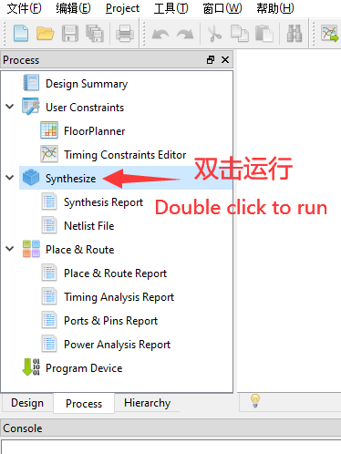
Synthesize
After finishing steps above, go to the "Process" interface, synthesize the edited file, which means running "Synthesize".
If the result is the same as shown below
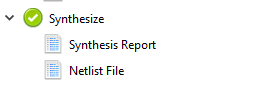
It means that there is no bug in our code, we can continue the next steps.
If there is some thing wrong, please fix by yourself.
Constrain
- Here we only constraint pins
The corresponding pins and ports are as follows form shows
The way to constain pins can refer to the Light led, it contains two ways to constain pins.
If you feel troublesome about the method above, you can copy the content in this page, and paste it in ".cst" file in this project (If there is no ".cst" file, just create a "physicsl constrains file").
| PORT | PIN | PORT | PIN |
|---|---|---|---|
| LED_B | 10 | LED_G | 11 |
| LED_R | 9 | LCD_B[4] | 24 |
| LCD_B[3] | 23 | LCD_B[2] | 22 |
| LCD_B[1] | 20 | LCD_B[0] | 19 |
| LCD_G[5] | 18 | LCD_G[4] | 17 |
| LCD_G[3] | 16 | LCD_G[2] | 15 |
| LCD_G[1] | 27 | LCD_G[0] | 28 |
| LCD_R[4] | 29 | LCD_R[3] | 30 |
| LCD_R[2] | 31 | LCD_R[1] | 34 |
| LCD_R[0] | 35 | LCD_DEN | 21 |
| LCD_SYNC | 32 | LCD_HYNC | 33 |
| LCD_CLK | 8 | XTAL_IN | 47 |
| nRST | 44 |
Place&Route
After constraining, we need to open IO mux to complete Place&Route.
Tick Project -> Configuration -> Place&Route -> Dual-Purpose Pin which is in the Menu Bar.
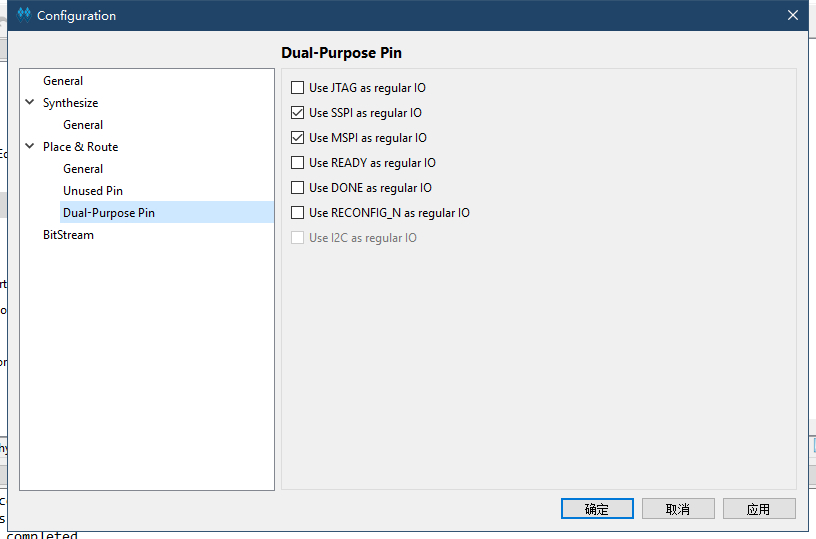
Then we can run Place&Route.
Program
Finishing Place&Route, we can download the generated .fs file to the development board to see color bar.
End
If you want the project, it can be found in this page : https://github.com/sipeed/TangNano-1K-examples.git
Now the tutorial ends, if you have any suggestions, just leave a message.
