

 English
Use of SP_RFID
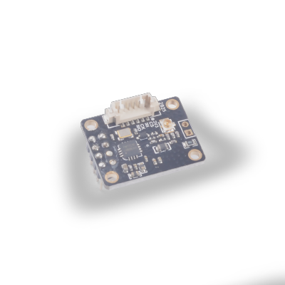
The FM17510 used in this module is a highly integrated non-contact reader/writer chip working at 13.56MHz. It supports the non-contact reader/writer mode conforming to the ISO/IEC 14443 TypeA protocol, and the program is compatible with MFRC522.
Parameters
- Support ISO/IEC 14443 TypeA reader mode
- Reader mode supports M1 encryption algorithm
- ISO14443 TYPEA supports communication rate 106kbps, 212kbps, 424kbps
- Support SPI serial interface, up to 10Mbps
- Voltage range 2.2V~3.6V
- 64Byte transmit and receive buffer FIFO
- Multiple low power consumption modes: Soft powerdown mode Hard powerdown mode
- Built-in CRC coprocessor
- Support low-power external card detection function
- Working voltage: 2.2V~3.6V
- Working temperature: -40°C~85°C
For detailed module information, please refer to RFID Specification and Data Manual
Instructions
Preparation: The development board with the latest firmware, sp_rfid module, M1 card.
Run: Connect the module, modify the configuration surrounded by config in Sample Code, and put the card close to the module antenna after running. See the card reading information printed by the terminal.
The procedure is as follows:
# Init module
MIFAREReader = MFRC522(spi1, cs)
# Scan for cards
(status, ataq) = MIFAREReader.MFRC522_Request(MIFAREReader.PICC_REQALL)
# Get uid
(status, uid) = MIFAREReader.MFRC522_Anticoll()
if status == MIFAREReader.MI_OK:
    # Bind card by uid
    MIFAREReader.MFRC522_SelectTag(uid)
    # Authenticate block 0x11 by key
    status = MIFAREReader.MFRC522_Auth(MIFAREReader.PICC_AUTHENT1A, 0x11, key, uid)
    if status == MIFAREReader.MI_OK:
        # Write 16 bytes from block 0x11
        MIFAREReader.MFRC522_Write(0x11, data)
        # Read 16 bytes from block 0x11
        MIFAREReader.MFRC522_Read(0x11)

'''output
>>> [Warning] function is used by fm.fpioa.GPIOHS20(pin:36)
Welcome to the MFRC522 data read/write example
Card detected type: 0x400
Card read UID: 110,159,46,15
Size: 8
Sector 11 will now be filled with 1~16:
4 backdata &0x0F == 0x0A 10
Data written
start to read
Sector 18 [0, 1, 2, 3, 4, 5, 6, 7, 8, 9, 10, 11, 12, 13, 14, 15]
Card detected type: 0x400
Card read UID: 110,159,46,15
Size: 8
Sector 11 will now be filled with 1~16:
4 backdata &0x0F == 0x0A 10
Error while writing
Data written
'''
It is mainly divided into several steps:
Create MFRC522 object (parameters: SPI object, chip selection pin).
Scan the card and get ATQA (i.e. card type code), ATQA corresponding card types are as follows:
| ATQA | Type |
| :----: | :----------------- |
| 0x4400 | Mifare_UltraLight |
| 0x0400 | Mifare_One(M1 S50) |
| 0x0200 | Mifare_One(M1 S70) |
| 0x0800 | Mifare_Pro(X) |
| 0x4403 | Mifare_DESFire |Get card UID
Binding the card through UID (anti-collision, to ensure that the selected card can execute the transaction correctly, and is not affected by another card on site)
Authenticate a certain sector in the card (M1 (S50) default password is 16 0xff)
Read/write card information (take one block (16 bytes) as the basic read and write unit)
