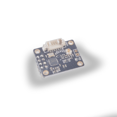
SP_RFID 的使用

该模块所采用的 FM17510 是一款高度集成的工作在 13.56MHz 下的非接触读写器芯片. 支持符合 ISO/IEC 14443 TypeA 协议的非接触读写器模式, 并且程序与 MFRC522 兼容.
参数
- 支持 ISO/IEC 14443 TypeA 读写器模式
- 读写器模式支持 M1 加密算法
- ISO14443 TYPEA 支持通讯速率 106kbps,212kbps,424kbps
- 支持 SPI 串行接口,最高 10Mbps
- 电压范围 2.2V~3.6V
- 64Byte 收发缓冲 FIFO
- 多种低功耗模式:Soft powerdown 模式 Hard powerdown 模式
- 内置 CRC 协处理器
- 支持低功耗外部卡片侦测功能
- 工作电压: 2.2V~3.6V
- 工作温度: -40°C~85°C
模块详细信息请参考RFID 规格书与数据手册
使用方法
准备: 已烧录最新固件的开发板, sp_rfid 模块, M1 卡片.
运行: 连接模块, 修改示例代码中 config 包围的配置, 运行后将卡片靠近模块天线, 可看到终端打印的读卡信息.
程序如下:
# Init module
MIFAREReader = MFRC522(spi1, cs)
# Scan for cards
(status, ataq) = MIFAREReader.MFRC522_Request(MIFAREReader.PICC_REQALL)
# Get uid
(status, uid) = MIFAREReader.MFRC522_Anticoll()
if status == MIFAREReader.MI_OK:
    # Bind card by uid
    MIFAREReader.MFRC522_SelectTag(uid)
    # Authenticate block 0x11 by key
    status = MIFAREReader.MFRC522_Auth(MIFAREReader.PICC_AUTHENT1A, 0x11, key, uid)
    if status == MIFAREReader.MI_OK:
        # Write 16 bytes from block 0x11
        MIFAREReader.MFRC522_Write(0x11, data)
        # Read 16 bytes from block 0x11
        MIFAREReader.MFRC522_Read(0x11)

'''output
>>> [Warning] function is used by fm.fpioa.GPIOHS20(pin:36)
Welcome to the MFRC522 data read/write example
Card detected type:  0x400
Card read UID: 110,159,46,15
Size:  8
Sector 11 will now be filled with 1~16:
4 backdata &0x0F == 0x0A 10
Data written
start to read
Sector 18 [0, 1, 2, 3, 4, 5, 6, 7, 8, 9, 10, 11, 12, 13, 14, 15]
Card detected type:  0x400
Card read UID: 110,159,46,15
Size:  8
Sector 11 will now be filled with 1~16:
4 backdata &0x0F == 0x0A 10
Error while writing
Data written
'''
主要分为几步:
创建 MFRC522 对象(参数为: SPI 对象, 片选脚).
扫描卡片并获取到 ATQA(即卡片类型码), ATQA 对应卡片类型如下:
| ATQA | Type |
| :----: | :----------------- |
| 0x4400 | Mifare_UltraLight |
| 0x0400 | Mifare_One(M1 S50) |
| 0x0200 | Mifare_One(M1 S70) |
| 0x0800 | Mifare_Pro(X) |
| 0x4403 | Mifare_DESFire |获取卡片 UID
通过 UID 绑定卡片(防碰撞, 确保所选卡能正确执行交易, 不受现场另一张卡的影响)
对卡片中某一扇区进行身份验证(M1(S50)默认密码为16个0xff)
读/写卡片信息(以一个块(16字节)为基本读写单位)


 中文
中文 Translate