English
MaixCAM MaixPy SPI Serial Peripheral Interface Usage Guide
Update history
| Date | Version | Author | Update content |
|---|---|---|---|
| 2025-08-08 | 1.1.0 | Neucrack | Refactored document, easier for beginners to understand |
| 2024-06-11 | 1.0.0 | iawak9lkm | Initial version of the document |
Prerequisites
Please first learn how to use the pinmap module to set pin functions.
To enable a pin for SPI functionality, first use pinmap to set the corresponding pin function to SPI.
Introduction to SPI
Earlier we introduced I2C, which enables one-to-many bus communication with only two wires. However, it has limitations, such as relatively low speed (typically 200k/400k). SPI (Serial Peripheral Interface) is also a one-to-many bus communication method, but it is faster and requires 4 wires for communication:
MISO: Master In Slave Out — this pin sends data in slave mode and receives data in master mode.MOSI: Master Out Slave In — this pin sends data in master mode and receives data in slave mode.SCK: Serial clock, output by the master and input to the slave.NSS/CS: Slave Select — chip select pin that allows the master to communicate individually with a specific slave device, avoiding conflicts on the data lines.
Common uses include:
- Reading and writing Flash memory.
- Communication between two devices.
- Protocol conversion, such as SPI to Ethernet.
- LCD display drivers.
- Outputting specific square waves, e.g., WS2812 LEDs. Apart from using GPIO control, SPI’s square-wave output capability can also be used to output specific waveforms.
In terms of protocol behavior, SPI generally works as follows:
SPI supports one master and multiple slaves. The master selects the slave to communicate with via the chip select pin. In most cases, a slave device needs only one chip select pin, while the master’s number of chip select pins equals the number of devices. When the chip select signal for a specific slave is enabled, that slave responds to all requests from the master; other slaves ignore all bus data.
SPI has four modes, determined by polarity (CPOL) and phase (CPHA) settings.
Polarity affects the clock signal level when the SPI bus is idle.
- CPOL = 1: Idle level is high.
- CPOL = 0: Idle level is low.
Phase determines which clock edge is used to sample data.
- CPHA = 0: Sampling starts at the first clock edge.
- CPHA = 1: Sampling starts at the second clock edge.
Combining polarity and phase yields the four SPI modes:
| Mode | CPOL | CPHA |
|---|---|---|
| 0 | 0 | 0 |
| 1 | 0 | 1 |
| 2 | 1 | 0 |
| 3 | 1 | 1 |
SPI usually supports both full-duplex and half-duplex communication.
SPI has no defined maximum transfer rate, no addressing scheme, no acknowledgment mechanism, and no flow control rules.
SPI is a very common communication interface, and through SPI, SoCs can control various peripheral devices.
Choosing the Right SPI to Use
First, we need to know which pins and SPI interfaces the device provides, as shown in the table:
| Device Model | Pin Diagram | Pin Multiplexing Description |
|---|---|---|
| MaixCAM | 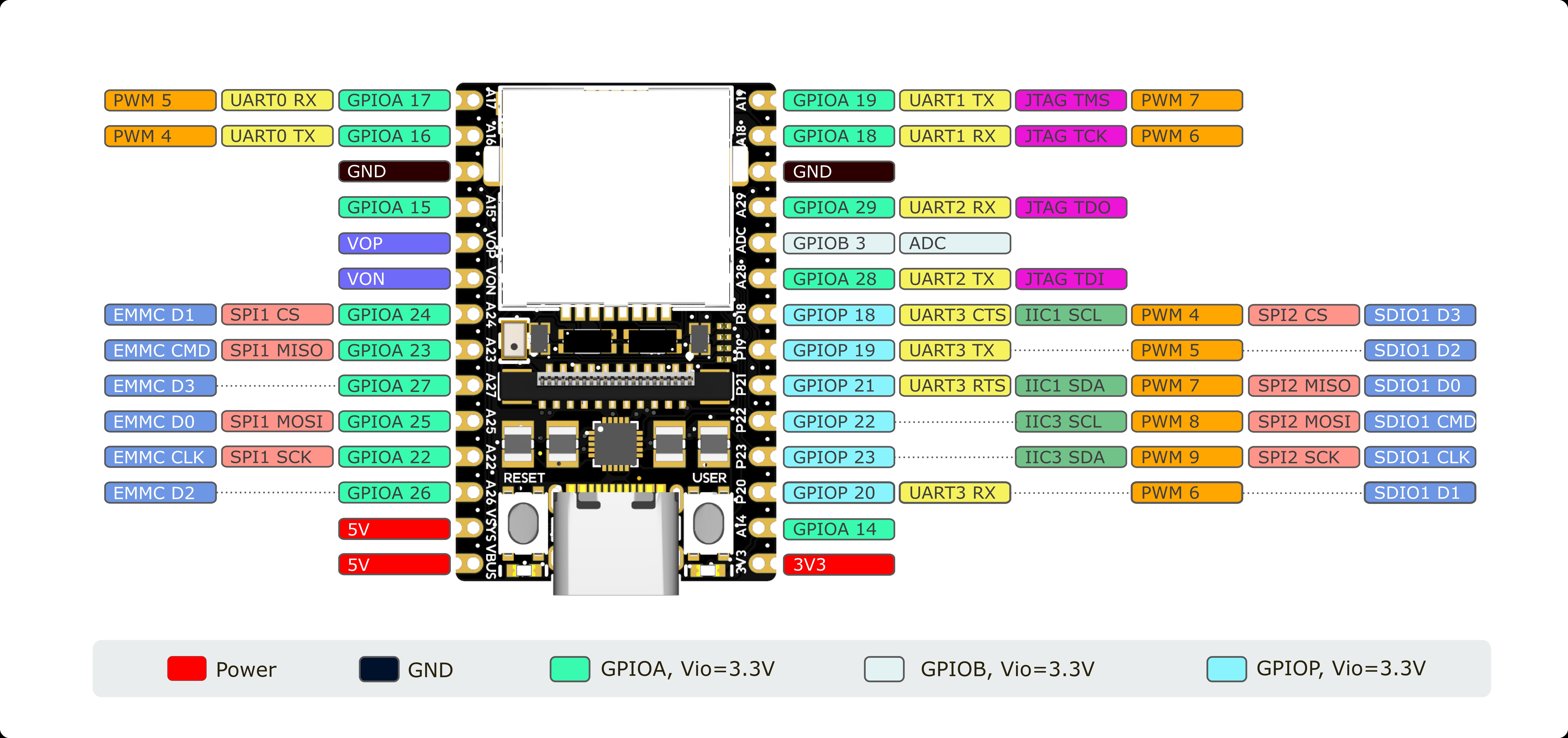 |
On the silkscreen, A24 is the pin name, SPI4_CS is the function name |
| MaixCAM-Pro | 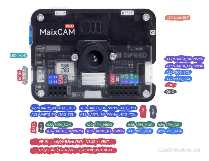 |
The first name, such as A24, is the pin name; SPI4_CS is the function name |
| MaixCAM2 | 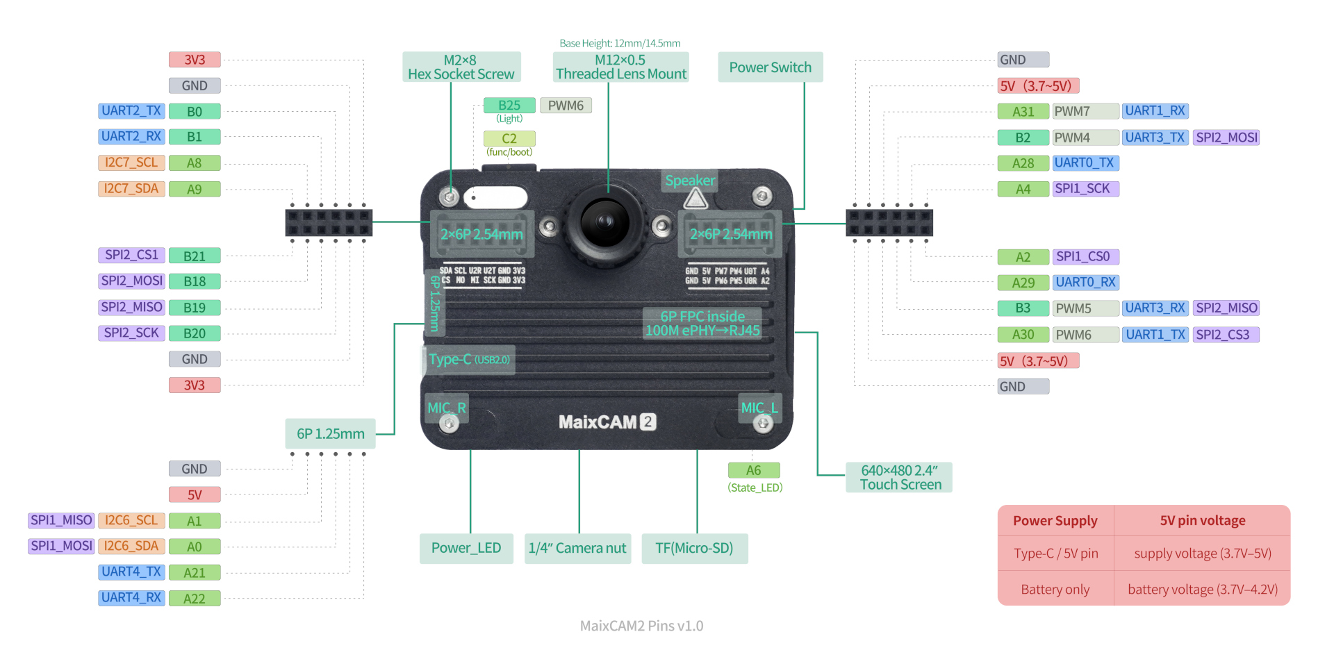 |
The first name, such as B21, is the pin name; SPI2_CS1 is the function name |
Note that pins may be used for other purposes by default; it’s best to avoid those pins. See the pinmap documentation for details.
For example:
MaixCAM/MaixCAM-Pro: Due to SPI peripheral limitations, they can only be used as SPI masters. MaixCAM's SPI currently does not support changing the active level of the hardware CS pin; all hardware SPI CS pins are active low. If you need another CS active level, configure it in the SPI API using a software CS pin and its active level. SPI4 is a software-simulated SPI, with a tested maximum speed of 1.25 MHz; usage is the same as hardware SPI.MaixCAM2: Has two hardware SPI interfaces by default; SPI2’s default function is SPI. SPI1’s pins require multiplexing setup first; seepinmapfor details.
Using SPI in MaixPy
To use SPI in MaixPy, first configure pinmap, then create an SPI object to communicate.
Here’s an example: connect the SPI’s MOSI and MISO together to perform a full-duplex loopback test.
from maix import spi, pinmap, sys, err

# get pin and SPI number according to device id
device_id = sys.device_id()
if device_id == "maixcam2":
    pin_function = {
        "B21": "SPI2_CS1",
        "B19": "SPI2_MISO",
        "B18": "SPI2_MOSI",
        "B20": "SPI2_SCK"
    }
    spi_id = 2
else:
    pin_function = {
        "A24": "SPI4_CS",
        "A23": "SPI4_MISO",
        "A25": "SPI4_MOSI",
        "A22": "SPI4_SCK"
    }
    spi_id = 4

for pin, func in pin_function.items():
    err.check_raise(pinmap.set_pin_function(pin, func), f"Failed set pin{pin} function to {func}")


spidev = spi.SPI(spi_id, spi.Mode.MASTER, 1250000)

### Example of full parameter passing, fully documention see API documentation.
# spidev = spi.SPI(id=4,                  # SPI ID
#                  mode=spi.Mode.MASTER,  # SPI mode
#                  freq=1250000,          # SPI speed
#                  polarity=0,            # CPOL 0/1, default is 0
#                  phase=0,               # CPHA 0/1, default is 0
#                  bits=8,                # Bits of SPI, default is 8
#                  hw_cs=-1,              # use default hardware cs.
#                  soft_cs="",            # If you want use soft cs, set GPIO name,
#                                         # e.g.  GPIOA19(MaixCAM), GPIOA2(MaixCAM2)
#                                         # you should set pinmap first by yourself.
#                  cs_active_low=true     # cs pin active low voltage level


b = bytes(range(0, 8))

res = spidev.write_read(b, len(b))
if res == b:
    print("loopback test succeed")
else:
    print("loopback test failed")
    print(f"send:{b}\nread:{res}")
More Examples
See MaixPy examples.
API Documentation
For more APIs, see the SPI API documentation