English
Using ADC in MaixCAM MaixPy
Update history
| Date | Version | Author | Update content |
|---|---|---|---|
| 2024-06-11 | 1.0.0 | iawak9lkm | Initial document |
Supported Devices
| Device | Supported |
|---|---|
| MaixCAM2 | ❌ |
| MaixCAM / MaixCAM-Pro | ✅ |
ADC Introduction
An ADC, which can also be called an analog-to-digital converter, converts an input voltage signal into an output digital signal. As the ADC converted digital signal itself does not have practical significance, only represents a relative size. Therefore, any ADC needs a reference analog as a conversion standard, the reference standard is generally the largest convertible signal size. The digital output of the ADC indicates the size of the input signal relative to the reference signal.
ADC peripherals generally have two main parameters: resolution and reference voltage.
- Resolution: The resolution of an ADC is expressed as the number of bits in a binary (or decimal) number. It describes the ability of the A/D converter to discriminate the input signal. Generally speaking, an A/D converter with n-bit output can distinguish 2^n different levels of input analog voltage, and the minimum value of input voltage that can be distinguished is 1/(2^n) of the full-scale input. For a given maximum input voltage, the more output bits, the higher the resolution.
- Reference Voltage: The ADC peripheral reference voltage is the voltage that is compared to a known voltage during AD conversion to find the value of the unknown voltage. The reference voltage can be thought of as the highest upper limit voltage and can be reduced to improve resolution when the signal voltage is low.
With the board's ADC, it is possible to capture external voltages and have the board verify that the voltages are up to snuff or perform specific tasks when specific voltages are detected (e.g., the ADC detects multiple buttons).
Using ADC in MaixPy
Using ADC with MaixPy is easy:
from maix.peripheral import adc
from maix import time

a = adc.ADC(0, adc.RES_BIT_12)

raw_data = a.read()
print(f"ADC raw data:{raw_data}")

time.sleep_ms(50)

vol = a.read_vol()
print(f"ADC vol:{vol}")
Use ADC0 to read the raw conversion data from it, or read the voltage data directly from it.
See the ADC API documentation for a detailed description of the ADC API.
Some notes on MaixCAM's ADC
MaixCAM elicits an IO that connects to the ADC, this IO is GPIO B3(For MaixCAM-Pro, B3 connected light LED, so ADC can't directly use).
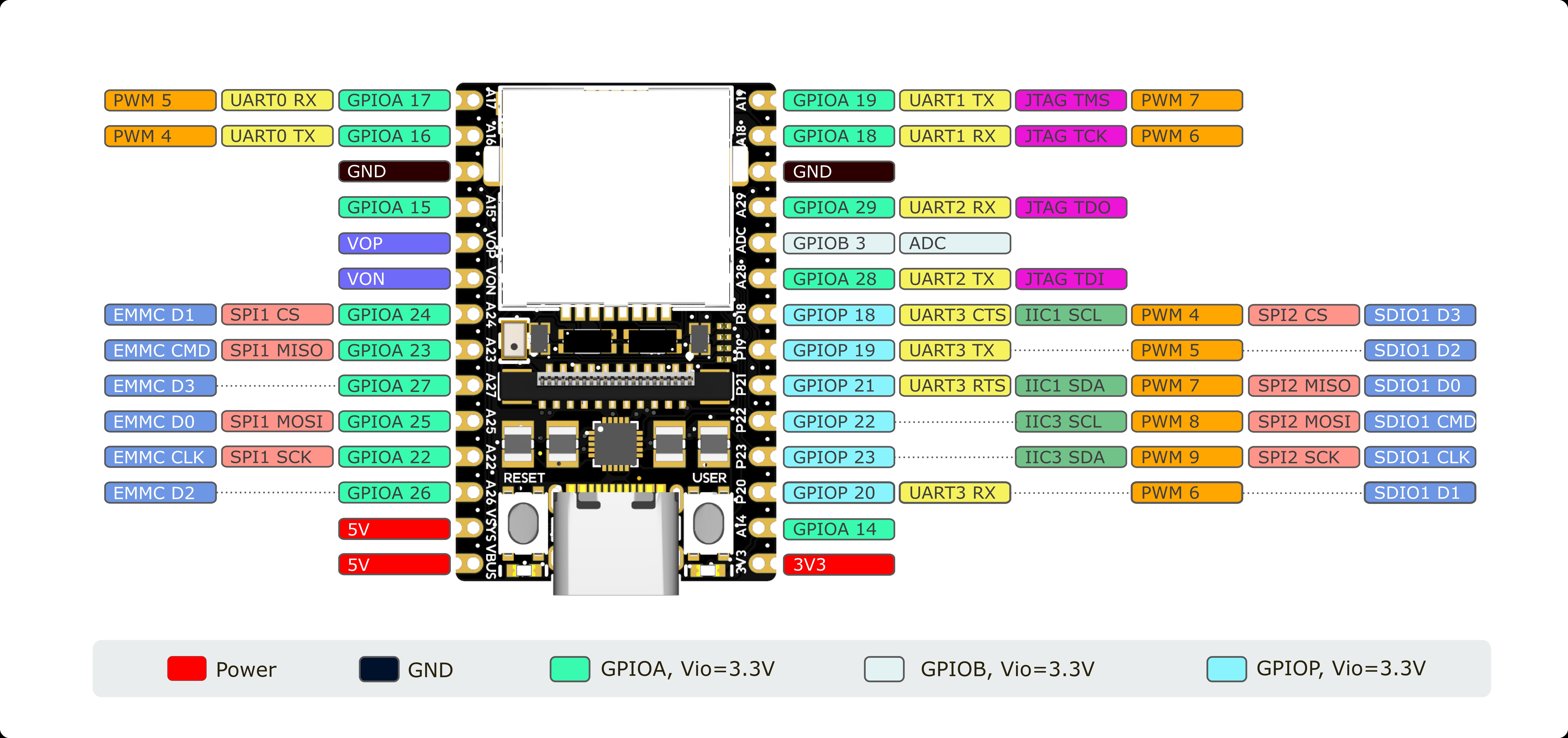
This IO is ADC by default and does not require additional configuration.
MaixCAM's ADC peripheral has a sampling accuracy of 12 bits, which means that the sampling output range is from 0 to 4095. The sampling accuracy is 1/4096 of the reference voltage.
The MaixCAM's ADC peripheral cannot scan at a frequency higher than 320K/s, which is the reason for the additional wait time between ADC samples in the previous example.
The MaixCAM's ADC peripheral has an internal reference voltage of 1.5V, which may vary slightly in actual use.Since the typical internal reference voltage is 1.5 V, the ADC range of Soc is 0 to 1.5 V. Since the ADC range of this range is small, MaixCAM has designed a voltage divider circuit for the ADC peripheral to increase the ADC range. The reference voltage Vin_max of this voltage divider circuit is about 4.6~5.0V, due to the error of resistor resistance in the circuit, the impedance of ADC external device, and the deviation of internal reference voltage. A higher precision default value has been chosen in the API, and there is generally no need to pass this parameter.

If you need high ADC accuracy, you can calculate the reference voltage for this voltage divider circuit by following the steps below:
You need to first measure to get the actual input voltage of ADC_PIN, which we call Vin.
Then you need to measure to get the actual input voltage at ADC1, which we call Vadc. The location of resistor R10 can be found in this BOM file.
You need to keep the same voltage input to ADC_PIN as in step 1 and then execute these commands in the shell:
echo 1 > /sys/class/cvi-saradc/cvi-saradc0/device/cv_saradc
cat /sys/class/cvi-saradc/cvi-saradc0/device/cv_saradc
This gives you the raw measured value of the ADC, which we call adc_data.
You need to know the resistance values of the resistors R6 and R10 in the picture, record them.Typically, the MaixCAM has a resistance value of 10KΩ (10 000Ω) for R6 and 5.1KΩ (5 100Ω) for R10.
Finally, you need to pass the results from the above steps to these python codes to get the range [0,Vin_max] of the ADC_PIN port.
def maixcam_get_vin_max(Vin:float, Vadc:float, adc_data:int, r6:int, r10:int, adc_max:int=4095):
    Vref = (Vadc/adc_data)*(adc_max+1)
    r3 = Vadc*r6/(Vin-Vadc)
    Vin_max = (Vref/r3)*(r6+r3)
    return Vin_max

Vin = 3.3		# step 1
Vadc = 1.06		# step 2
adc_data=2700	# step 3
r6=10000		# step 4
r10=5100		# step 4

if __name__ == '__main__':
    print(maixcam_get_vin_max(Vin, Vadc, adc_data, r6, r10))
Now pass the result to the third parameter of
adc.ADC()and you will get a highly accurate ADC.