

 English
Using Tang's GPIO
Create a new project
In the Menubar goto Project -> New Project or uses the shortcut key Ctrl+Alt+P.
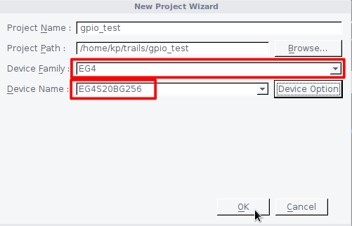
Fill in the Project Name and Project Path fields. Note that you may create a new directory (such as "gpio_test") by clicking on Browse and then clicking on the Create New Folder icon in the "choose a directory" window. It's generally recommended to keep each project in its separate directory.
Select Device Family and Device Name for Tang Primer as shown below. When done, click OK.
Create a new HDL source file.
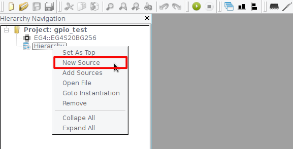
Right-click on Hierarchy and click on New Source to make a new HDL source file.
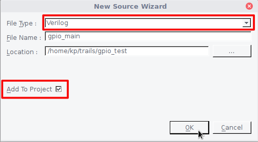
Select the HDL File Type and enter a source file name in the File Name field. Check Add To Project to add this file to your project. Click OK.
Copy the following code into a text editor and Save it, as shown in the following image.
module gpio_main
    (
    	input wire RST_N,
    	output wire R_LED
    );

assign R_LED = RST_N;

endmodule

Now we need to assign physical Pins to our IO ports. In the FPGA Flow pane, if there is a "+" to the left of User Constraints, click on the "+" to show the IO Constraint and SDC Constraint items. Double click on IO Constraint to open the IO Constraint Dialog.

Select the IO Bank and Pin Location for Tang's onboard LED and Button then save it as an adc file in the project.


Click on Run Icon to start the compilation process.

Plugin your Tang Primer board to USB and click on Download icon to open Download Dialog.

Make sure your device detected by TD IDE. Add generated bitstream file by clicking on the Add button. Click on the Run button to start the download process.

Download the Bitstream into SPI Flash to make your design run after a power reset.

